In previous tutorials, we discussed two of the most important building blocks of an audio system: microphones and speakers.
As a general overview, an audio system is designed to:
- Receive audio signals, typically via a microphone
- Record audio into a storage device, such as a computer file
- Transmit audio, either through wired or wireless communication channels
- Reproduce audio signals, via speakers
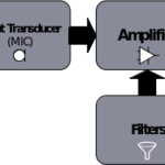
Audio circuits perform signal processing, essentially transforming sound waves into electrical signals, which can further be altered through amplifying, filtering, or mixing. These signals can also be stored and reproduced.

An audio system
Audio filters are one part of this system, working as amplifiers or passive circuits with distinct frequency responses. Much like microphones and speakers, these filters are an important part of the basic building blocks of an audio system. They can amplify or attenuate a range of frequencies from the audio input.
However, these filters are distinct from a simple audio amplifier or input source, which does not have a frequency-dependent functioning. It augments the full input audio signal regardless of its frequency. But, an audio filter is a frequency-dependent amplifier that works in the range of 0 Hz to beyond 20 kHz. By specifically amplifying or attenuating a range of frequencies in the audio signal, it’s possible to enhance the audio input tone.
An audio crossover and an equalizer are types of audio filters. The audio crossover is an electronic filter used to split the input audio signal into different frequency ranges, which are then sent to different drivers (such as tweeter, mid-range, and woofer speakers). The audio equalizer is an electronic filter used to amplify the audio signal, according to a frequency-dependent function. An equalizer’s output has different amplified levels for different frequencies.
The crossover and equalizer play a major role in the audio devices. Next, we’ll discuss the types of filters available and their features.
Types of filters
Audio filters are the electronic circuits designed to amplify or attenuate a certain range of frequency components. They serve as a unique type of amplifier or a passive circuit with frequency-dependent outputs. Essentially, they help eliminate any unwanted noise from an audio signal, improving the tone of the output.
These filters play an important role in telecommunication and audio electronics and can be classified based on their design, frequency response, or both.
Design
Audio filters classified based on their design are either passive or active filers. An electronic device that requires a power supply for its operation is an active component, and one that does not is a passive component.
Active filters – require a power source and are designed using active components, such as transistors or operational amplifiers (op-amps). The transistors or operational amplifiers require a DC power source for their biasing. By using active components, there remains no need to use inductance to construct the filter, which reduces the size and cost of the circuit and improves the efficiency of the filter.
Passive filters – require no power source to operate, these filters are designed using passive components, such as resistors, capacitors, or inductances. The impedance of the capacitors and inductances is frequency-dependent, so the filter can be designed using resistor-capacitor, resistor-inductance, or resistor-capacitor-inductor combinations.
Frequency response
Audio filters can also be classified based on their frequency response, which refers to the range of frequencies that are amplified or allowed to pass by a filter (the pass band). The pass-band is the region in the frequency curve of a filter where the circuit’s voltage or power is at max.
Depending on the frequency band, there are several types of filters, including high-pass, low-pass, bandpass, bandstop, notch, all-pass, and equalization.
Let’s review each one…
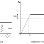
High-pass filter (HPF) – passes signals with a frequency higher than a cutoff frequency and blocks all of the signals lower than a cut-off frequency. The cut-off frequency is when the signal’s voltage or amplitude falls to 0.707 or 3 dB of the pass-band voltage. At this point, the power output of the circuit begins falling.

The typical frequency curve of a high-pass filter.
As can be noted from this graph, the low-frequency signals are not completely attenuated at the cut-off frequency. But those frequencies that break through the high-pass filter have very little gain. Technically, there’s a “roll-off frequency” at the cut-off.
Low-pass filter – passes signals with a frequency lower than the cut-off and blocks those frequencies higher than it.

The frequency response of a low-pass filter.
As can be noted from this graph, the high-frequency signals are not completely attenuated at the cut-off frequency. Those frequencies that break through the low-pass filter have little gain.
Band-pass filter – only passes frequencies within a certain cut-off range and rejects those that are outside of the range. It has two cut-off frequencies: the lower and the upper cut-off. The center frequency and bandwidth of this filter determine the lower and upper cut-off frequencies.

The frequency response of a band-stop filter.
Band-stop filter – passes all frequencies except for a specific range. This means it passes all of the signal frequencies below its lower cut-off and above its higher cut-off — but not frequencies between the lower and higher cut-off. The higher and lower cut-off frequencies are deviations of the center frequency for which the gain of the filter circuit is ideally zero (practically minimum).
Notch filter – a bandstop filter with an extremely narrow stop-band. As a result, these filters offer a high-quality factor.
All-pass filter – passes all the frequencies equal in gain but modifies the phase relationship between them. The output of frequency ranges also display phase differences between them.

The phase-shifted frequency response of an all-pass filter.
Equalizer filter – never completely attenuates or passes a specific range of frequencies but amplifies frequencies based on a frequency-dependent function.
Design + frequency response
Filters can also be classified based on both their design and frequency response. This includes passive or active high-pass, passive or active low-pass, passive or active band-pass, and passive or active band-stop filters.
Passive high-pass filter – blocks lower frequency signals while allowing higher frequency ones. This type of filter is typically used to direct the high-frequency elements of an audio signal to a tweeter and is often designed using a resistor–capacitor (RC) network — an electric circuit composed of resistors and capacitors.
The passive high-pass has no bandwidth limitation and can be designed by selecting the resistor and capacitor’s values. As a passive filter, it requires no power source for DC biasing, so it has few components. It offers a high-current output but is unable to amplify audio signals.
Although an inductor can be used as part of the filter’s design, they’re costly and bulky.

A simple circuit of a passive high-pass filter.
For this RC network, the cut-off frequency relates to the resistor and capacitor as follows:
fh = 1/ (2πRC)
By setting the resistor and capacitor’s value and the preferred cut-off frequency, it’s possible to design a high-pass filter. In the above circuit, the cut-off frequency is about 160 Hz. A high-pass filter will pass all the frequencies higher than 160 Hz and attenuate the frequencies lower than it.
Active high-pass filter – can be designed using transistors or operational amplifiers. The filter in the circuit diagram uses op-amp at the RC network’s output, making it an active filter. An op-amp is an integrated circuit that can amplify weak electric signals. It has two high-impedance inputs. So, while the RC network blocks any low-frequency elements, the op-amp amplifies a permitted frequency range.
In this case, the RC network is connected to the op-amp’s non-inverting input pin, so its output is not inverted. When it’s connected to the op-amp’s inverting pin, the output audio signal is phased by 180 degrees from the input audio signal.

A simple circuit of an active high-pass filter.
The active high-pass filter has a high, non-unity gain, which means the output audio signal is noise-free and well amplified. It also has no loading effect. The op-amp has a high input and a low-output impedance, so loading at the source is also not an issue. However, because of the op-amp, the filter’s circuit will have bandwidth limitations.
Typically, these filters are small and compact. However, an active filter design involves more components that require a DC source for their biasing and it will need an external power supply to operate.
Passive low-pass filter – the input signal is passed through a resistor (instead of a capacitor like with a high-pass filter). The capacitor is connected between the resistor and the ground.
However, passive low-pass filters can have different designs using:
- An RC or a resistor–inductor (RL) network for a first-order filter
- A resistor–inductor-capacitor (RLC) network for a second-order filter
- Combining several first-order filters in a series for a high-order, more precise audio signal
So, for example, a first-order filter has one capacitor or one inductor, which affects the filter’s frequency response. Whereas, a second-order filter has two RC filter sections — such as two capacitors or two inductors — which affect its frequency response.

A circuit of a first-order, passive low-pass filter.
The passive low-pass filter allows all frequencies lower than the cut-off frequency to pass but attenuates those higher than the cut-off. These filters do not have a bandwidth limitation and require no power source to operate. They’re typically used to drive low-frequency elements of an audio signal to a woofer.
Active low-pass filter – uses an op-amp or a transistor amplifier at its output and before the use of a low-pass RC, RL, RLC, or multiple-order passive filters. An op-amp amplifies the low-frequency elements before delivering the sound to a power amplifier or speakers.
The gain delivered via the op-amp is the main advantage of this filter — plus it reduces any high-frequency noise or distortions. But it has bandwidth limitations and requires a DC source for biasing the amps or the transistor circuit.
Passive band-pass filter – designed by combining a low and high-pass filter, and usually designed using an RLC network.

A circuit of a first-order, passive band-pass filter.
In this circuit, a high-pass filter is connected in series with a low-pass filter.
Note:
- The high-pass filter’s cut-off frequency is the band-pass filter’s lower cut-off frequency
- The low-pass filter’s cut-off frequency is the band-pass filter’s higher cut-off frequency
- So, only the frequencies between these two cut-off frequencies are allowed to pass at the filter’s output
These filters are typically used to direct a specific range of frequencies to mid-range drivers. As there are several components in their construction, these filters are big and heavy.
Active band-pass filter – has an op-amp or transistor amplifier connected before its output and after the passive band-pass circuit. The op-amp amplifies the permitted band of frequencies, and its bandwidth must match that of the band-pass filter.

A circuit of a first-order passive band-pass filter.
Passive band-stop filter – attenuates a range of frequencies, allowing both those lower and higher than its two cut-off frequencies to pass. A first-order, passive band-stop filter is usually designed using an RLC network, where the input signal is first passed through a resistor. The LC network is connected between the resistor and the ground.
This circuit combines that of the high and low-pass filters.
Note:
- The high-pass filter’s cut-off frequency is the band-stop filter’s higher cut-off frequency
- The low-pass filter’s cut-off frequency is the band-stop filter’s lower cut-off frequency
- So, only the frequencies that exclude those that are between the high and low-pass filters’ cut-off frequencies are allowed to pass at the output
These filters are also called band-reject, band-elimination, and T-notch filters.
Active band-stop filters – has an op-amp or transistor amplifier at the output, which amplifies the allowed frequency signals before they’re delivered to a power amplifier or an audio driver. This op-amp using must have a bandwidth that matches the band-stop filter’s desired frequency curve.
Terms
Here are a few terms that are frequently used in relation to audio filters.
Bandwidth: the range of frequencies allowed to pass through the filter, or the difference in upper and lower cut-off frequencies. Sometimes referred to as the pass-band bandwidth, the bandwidth determines the frequency response of the filter within the set range of frequencies.

The bandwidth of an audio filter based on its frequency curve.
Quality factor (Q-factor): the losses in the resonator circuit. The ratio of the energy stored at the resonator to the energy supplied per cycle to maintain a signal’s constant amplitude. The greater the Q means the fewer the losses, and vice versa.
Q = (Energy stored / Energy lost per cycle)
In terms of bandwidth, the Q is determined using this equation:
Q = (fc/ BW)
Where…
fc = Resonant frequency
BW = Bandwidth or resonance width
The Q-factor can be determined using the frequency curve of the audio filter…

The Q-factor of an audio filter from its frequency curve.
You may also like:

Filed Under: Audio, Tutorials

Questions related to this article?
👉Ask and discuss on EDAboard.com and Electro-Tech-Online.com forums.
Tell Us What You Think!!
You must be logged in to post a comment.