
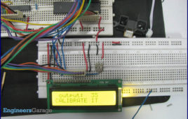
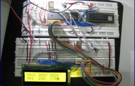
Real time clock (RTC) is widely used in many application to provide accurate time. This article explains the making of a simple digital clock using RTC DS 12C887 and 8051 microcontroller (AT89C51). The output is displayed on an LCD. This clock also has a provision of setting time at any instant. The clock uses the concept of our earlier articles of interfacing RTC DS12C887 with microcontroller. The clock described here uses the method of polling for running. For further details on interfacing RTC DS12C887 with AT89C51 using polling, refer RTC interfacing. The free source code for the program is available in C. The circuit diagram shows the connection of RTC with the microcontroller. Port P2 is used as data port for LCD; port P0 of the microcontroller is used as data port of RTCDS12C887. The pins P1^0, P1^1, P1^2, P1^3, P1^4, P1^5, P1^6 of controller AT89C51 are configured as reset, rs, rw, e, dig_hr1, dig_min1, start pins respectively.
How to Interface RTC DS12C887 with 8051 microcontroller (AT89C51)- (Part 33/45)

The purpose of an RTC or a real time clock is to provide precise time and date which can be used for various applications. RTC is an electronic device in the form [[wysiwyg_imageupload::]]of an Integrated Chip (IC) available in various packaging options. It is powered by an internal lithium battery. As a result of which even if the power of the system is turned off, the RTC clock keeps running. They play a very important role in the real time systems like digital clock, attendance system, digital camera etc. The article presented here shows how RTC can be interfaced with the microcontroller AT89C51. It explores the basic operation of accessing the internal registers and extracting time from the RTC. The time is displayed on the hyper terminal using serial communication. The RTC used here is DS 12C887. 89C51 microcontroller is a very commonly used controller from the family of 8051 series of microcontroller.
How to interface Sharp’s distance sensor with 8051 microcontroller (AT89C51)- (Part 32/45)
This project uses Sharp’s distance measuring sensors for exact distance measurement. Advanced measurement techniques make these sensors more reliable. [[wysiwyg_imageupload::]]They have higher precision since they are less influenced by the color and reflectivity of the reflected object. They use a focused beam to indicate the presence and location of an object in a particular range depending on the variant of the sensor. Typical ranges for different sharp sensors vary from 4 cm to 150 cm.The project works on the same principle as that of simple IR sensor based distance measurement. The analog output of the sensor is directly converted to digital by employing an ADC0804 interfaced with AT89C51. The measured distance is also displayed on an LCD screen. This project is used for detecting humans and objects in several devices, security systems and robotics applications. It can be employed for sanitary purposes in electronic faucets, flush levers, soap dispensers etc. This project mainly consists of three units: a sensor unit, an ADC component and the LCD module.
How to interface LDR with ADC0808 using interrupt clock from 8051 microcontroller (AT89C51)- (Part 26/45)

This circuit demonstrates the principle and operation of interfacing an LDR with ADC0808 using the controller AT89C51. This is an 8 channel ADC i.e., it can take [[wysiwyg_imageupload::]]eight input signals. The output is displayed on the LCD. ADC0808 is an 8-bit resolution IC with eight input pins. LDR is used to provide the analog input. The output of the LDR is displayed on a 16×2 LCD. A clock of frequency 500 KHz is generated using Timer0 in the interrupt mode. To enable the interrupt, the value of the register IE is set to 0x82.The output pins of ADC are connected to the port P0 of the AT89C51. The pin10 of the ADC is connected to pin8 (P1.7) of the controller for clock input. ALE, pin22 of the ADC is connected to pin1 (P1.0) of controller. OE, pin9 of the ADC is connected to pin4 (P1.3) of controller. SC, pin6 of the ADC is connected to pin2 (P1.1) of the controller. EOC, pin number 7 is connected to pin 3 (P1.2) of controller.
Interfacing ADC0808 with Serial port (RS232) & 8051 microcontroller using clock from D-flip flop- (Part 29/45)
Many a times, it is required to receive signals from different sensors and to monitor the related data on a PC. In such cases, an ADC is required to convert analog [[wysiwyg_imageupload::]]signals, from the sensors, to digital pattern. Also, this data transfer can be carried out through the serial port, RS232, of the computer. This circuit demonstrates the principle and operation ADC0808 interfacing using serial port via 8051 microcontroller (AT89C51). The circuit is divided into four parts: clock, ADC, controller and serial port. This circuit can be used as an intermediate module in many important applications.ADC0808 which is an 8-bit resolution ADC has eight analog input pins to take inputs. The circuit uses a preset for providing the analog input. The clock for driving the ADC0808 is taken from the crystal of the microcontroller. The controller AT89C51 uses a crystal of frequency 11.0592 MHz. As this frequency is too high for the ADC, it is divided using a D flip-flop and then given to the ADC0808.
Digital alarm clock with thermometer using 8051 microcontroller (AT89C51)
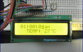
Celsius scale thermometer displays the ambient temperature through a LCD display. It consists of two sections. One is that which senses the temperature. This is a temperature sensor LM 35. The other section converts the temperature value into a suitable number in Celsius scale which is done by the ADC0804. A digital thermometer can be easily made by interfacing…
Electronic voting machine using seven segment multiplexing with 8051 microcontroller (AT89C51)
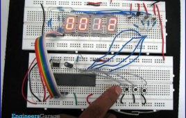
This topic presents a basic approach to develop an electronic machine. The idea is to display the count of votes on a set of seven segment displays. A set of [[wysiwyg_imageupload::]]switches are provided through which a user can cast vote. After every cast of vote, the subsequent count can be seen on the seven segments. The segments and switches are controlled through AT89C51. For every candidate, a segment has been provided.This voting machine is designed for four candidates. The provision of casting vote has been provided by means of four tactile switches. These switches take manual inputs from the user and transfer them to the pins of controller. Based on these inputs, the vote count for different candidates is increased by AT89C51.Read more to find out how to program and design such a circuit.
How to interface computer’s Serial Port (RS232) with 8051 microcontroller (AT89C51)- (Part 21/45)

Several devices collect data from sensors and need to send it to another unit, like a computer, for further processing. Data transfer/communication is generally [[wysiwyg_imageupload::]]done in two ways: parallel and serial. In the parallel mode, data transfer is fast and uses more number of lines. This mode is good for short range data transfer.Serial communication on the other hand, uses only one or two data lines to transfer data and is generally used for long distance communication. In serial communication the data is sent as one bit at a time. This article describes the interfacing of 8051 microcontroller (AT89C51) with a computer via serial port, RS232. Serial communication is commonly used in applications such as industrial automation systems, scientific analysis and certain consumer products. The microcontroller AT89C51 has an inbuilt UART for carrying out serial communication. The serial communication is done in the asynchronous mode. A serial port, like other PC ports, is a physical interface to establish data transfer between computer and an external hardware or device. This transfer, through serial port, takes place bit by bit.
Dual message display on LCD using 8051 microcontroller (AT89C51)
This article presents an interesting approach for sound activated display system. This system displays two different messages for odd and even number of [[wysiwyg_imageupload::]]sounds. When the sound is produced for the first time the first message is displayed on the LCD. At the second sound, a second message is displayed. The first message reappears at the third sound. Thus alternate messages are displayed every time a sound, say clap, is detected by the system. The project is build around the 8051 microcontroller (AT89C51) along with LCD and a condenser microphone.The circuit consists of four major modules, namely, a sound sensor, an amplifying circuit, a control circuit and a display module. A switching circuit is also employed after the amplifier. Any sound, say clap, is detected by a microphone (condenser mic) which acts as the sound sensor. This mic is connected to a two stage transistor amplifier. The mic output is thus amplified to a suitable level so that it can be detected at the TTL logic.
Liquid/Water Level Indicator with Alarm using 8051 Microcontroller (AT89C51)
This article illustrates the construction and working of a liquid level indicator. Such an indicator is used in tanks to indicate the level of liquids and alert us when [[wysiwyg_imageupload::]]the tank is full. So by this circuit we can monitor the various levels of the tank and can avoid spillage of water and also we can configure our supplies according to the various levels of tank. Such module or circuit can be installed in big buildings where manual monitor of tanks is difficult and its indicator can be placed at some centralised place. Initially when the tank is empty LCD will show the message VACANT. As the tank starts filling up wire at different levels get some positive voltage, due to conducting nature of water. This voltage is then fed to their corresponding pins on controller. When level reaches to quarter level, LCD displays the messageQUARTER. On further rise of level, HALF and 3/4 QUARTER are displayed on LCD.
How to generate sound using 8051 microcontroller (AT89C51)- (Part 18/45)
Sound is a function of frequency. This concept has been used to generate sound from the microcontroller. Different types of sounds can be produced by varying [[wysiwyg_imageupload::]]the frequency.Frequencies are generated by using Timer1 of microcontroller. Timer is used to produce exact delays and by toggling the output pin we can generate the desired frequencies. These frequencies are then fed to a particular pin (here Pin 0 of port1) which is connected to speaker. The output can be heard on the speaker. By combining the different frequencies we can generate different tones and alarms.
How to interface three input channels of ADC0808 using 8051 microcontrollers (AT89C51)- (Part 24/45)
Many applications need to measure and/or monitor the physical quantities like temperature, pressure, light intensity etc. The sensors used to measure the physical [[wysiwyg_imageupload::]]quantities give the output in analog form, which are converted to digital through an ADC for further processing. This circuit demonstrates the principle and operation of interfacing ADC0808 with three LDR. The output of the sensor is displayed on the LCD. The external clock needed by the ADC0808 is provided by the controller using interrupt. The output is displayed on the LCD. The circuit is divided into four parts: LDR, ADC, 8051 microcontroller and LCD. Its applications could be measuring and monitoring the light intensity level. ADC0808 is an 8-bit resolution ADC with eight input channels. At any point of time only one input can be read. The output of LDRs are used as inputs. An LDR will detect the intensity of light and generate voltage depending upon light intensity. A clock of frequency 500 KHz is generated using Timer0 in the interrupt mode. To enable the interrupt, the value of the register IE is set to 0x82.
How to interface ADC0808 using clock from 8051 microcontroller (AT89C51)- (Part 25/45)
An analog-to-digital converter is a device which converts continuous signals to discrete digital numbers. Typically, an ADC is an electronic device that converts [[wysiwyg_imageupload::]]an input analog voltage (or current) to a digital number proportional to the magnitude of the voltage or current. This circuit demonstrates the interfacing ofADC0808 using 8051 microcontroller (AT89C51). The digital output is taken on a set of LEDs. This is an intermediate circuit which finds several applications. This circuit depicts a way to provide the external clock, required for ADC, from the microcontroller.Analog-to-digital converters are among the most widely used devices for data acquisition. Digital computers use binary values, but in physical world everything is analog. Therefore, we need an analog-to-digital converter to translate these analog signals to digital signals.An ADC has n-bit resolution where n can be 8,10,12,16 etc. The ADC chips are either parallel or serial. Parallel ADC has 8 or more pins dedicated to bring out the binary data. ADC0808 is such a parallel ADC with 8-bit resolution.
How to interface ADC0808 with 8051 microcontroller (AT89C51) using clock from D-flip flop- (Part 28/45)
An analog-to-digital converter is a device which converts continuous signals to discrete digital numbers. Typically, an ADC is an electronic device that converts [[wysiwyg_imageupload::]]an input analog voltage (or current) to a digital number proportional to the magnitude of the voltage or current. This circuit demonstrates the interfacing of ADC0808 with 8051 microcontroller (AT89C51). The output is taken on the LEDs. This is an intermediate circuit, which finds lot of applications. ADC0808 needs an external clock to run. The circuit describes how a D-flip flop can be used to provide the external clock. Analog-to-digital converters are among the most widely used devices for data acquisition. Digital computers use binary values, but in physical world everything is analog. Therefore, we need an analog-to-digital converter to translate the analog signals to digital signals. An ADC has n-bit resolution where n can be 8,10,12,16 etc. The ADC chips are either parallel or serial. In parallel ADC we have 8 or more pins dedicated to bringing out the binary data. ADC0808 is a parallel ADC with 8-bit resolution.
Interfacing ADC0804 with Serial port (RS232) using 8051 micocontroller (AT89C51)- (Part 23/45)
This circuit demonstrates the principle and operation of collecting data from ADC0804 and sending it to PC via serial communication using 8051 microcontroller [[wysiwyg_imageupload::]](AT89C51). The circuit is divided into three parts: ADC, Controller and Serial Port. This circuit can be used as an intermediate in many applications.ADC0804 which is an 8-bit resolution ADC has only one input channel connected to variable resistance (preset) to give the analog input. In place of preset, analog input from a sensor can also be used. The output pins of the ADC are connected to port P1 of the microcontroller. Write (WR) pin 3 is connected to P2.0 i.e. pin 21 of controller. Read (RD) pin 2 is connected to P2.1 i.e. pin 22 of controller. Interrupt (INTR) pin 5 is connected to P2.2 i.e. pin 23 of controller. Read more to find out how this 8051based project works and what aspects of coding does it cover.
Distance measurement using InfraRed sensor with ADC0804 & 8051 microcontroller (AT89C51)
Infrared sensors find numerous applications in electronic systems. Commonly used as obstacle detector, their output is used in digital form (high & low logic) by [[wysiwyg_imageupload::]]employing a comparator. This topic explains a way to use the sensor’s output in its original analog form. Thus, along with detecting an obstacle, its exact distance can also be obtained. This is achieved by processing the output of IR sensor through an ADC0804 (analog to digital converter). The ADC is calibrated to get almost accurate distance measurement.The measured distance is also displayed on an LCD screen. The ADC0804 and LCD are interfaced with 8051 microcontroller (AT89C51) to perform these operations. The major drawback of IR based sensors is their capability of detecting short distances. Read more to find out how the circuit is assembled and coded. Also find out an interesting flash depicting the working of the sensor.
Clap counter using 8051 microcontroller (AT89C51)
This article explains the concept behind interfacing a sound sensor with the 8051 microcontroller (AT89C51). This project increases the count by one every time a sound is produced. It works well with the sound of a clap. The number of claps is displayed on an LCD module. The circuit consists of four modules, namely, a sound sensor, an amplifying circuit, a control circuit and a display module. The code for interfacing the sound sensor with the MCU is written in C language.The connections of different modules are shown in the circuit diagram. The data pins of the LCD are connected to port P2, while the control pins (RS, R/W & EN) are connected to pins 1-3 of port P1of AT89C51, respectively. The microcontroller receives sound pulses through the first pin of port P0.A condenser microphone is used to sense the sound produced by the clap. This mic is connected to a two stage transistor amplifier.
Sound operated display on LCD using 8051 microcontroller
This is an interesting idea in which a message is displayed on an LCD screen whenever a sound is produced. The message remains on LCD for a short duration of [[wysiwyg_imageupload::]]time and then disappears. This topic demonstrates the interfacing of a sound operated circuit and LCD display with the 8051 microcontroller (AT89C51). The circuit can be used to display welcome message at entrance; or warning messages at public places. It can also be used to aid communication for deaf and dumb people.The circuit consists of four major modules, namely, a sound sensor, an amplifying circuit, a control circuit and a display module. A switching circuit is also employed after the amplifier.Any sound, say clap, is detected by a microphone (condenser mic) which acts as the sound sensor. This mic is connected to a two stage transistor amplifier. The mic output is thus amplified to a suitable level so that it can be detected at the TTL logic.
Celsius and Fahrenheit scale digital thermometer using 8051 microcontroller (AT89C51)
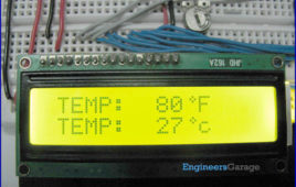
Fahrenheit scale digital thermometer is a temperature indicator which displays temperature in Fahrenheit scale. It is similar to Celsius scale digital thermometer, [[wysiwyg_imageupload::]]except a little modification in the microcontroller program. The temperature sensed in Celsius scale in the Celsius scale thermometer project is converted into the Fahrenheit scale temperature just by using the Celsius to Fahrenheit conversion formulae. This project also uses 8051 microcontroller (AT89C51).A digital thermometer can be easily made by interfacing a temperature sensor to the microcontroller AT89C51. The temperature sensor used in the project isLM35. The LM 35 IC generates a 10mV variation to its output voltage for every degree Celsius change in temperature. The Output of the temperature sensor is analog in nature so we need an analog to digital convertor for converting the analog input to its equivalent binary output. The ADC 0804 is the analog to digital convertor IC used in the project. 0804 is a single channel convertor which converts the analog input up to a range of 5V to an equivalent 8-bit binary output.
Celsius scale digital thermometer using 8051 microcontroller (AT89C51)
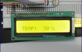
Celsius scale thermometer displays the ambient temperature through a LCD display. It consists of two sections. One is that which senses the temperature. This is a temperature sensor LM 35. The other section converts the temperature value into a suitable number in Celsius scale which is done by the ADC0804. A digital thermometer can be easily made by interfacing…