In the previous articles, we learned about resistors, capacitors, and inductors. When discussing inductors, we had talked about mutual inductance, which is the result of magnetic coupling between two inductors. If two inductors are used in a circuit to function as ‘inductors,’ this mutual inductance or any magnetic coupling between the two inductors is generally unwanted. However, the magnetic coupling between the two inductors can be useful. A transformer is one such electrical and electronic device where magnetic coupling between inductors is utilized.
Electromagnetic induction
If two wires are placed close to each other and one carries a fluctuating current, then a current is also induced in the other wire. If instead of wires, two coils have a common axis, the induced current is much higher. The current is induced from one wire or coil to another on the passage of fluctuating current in one of them due to magnetic coupling between them. This phenomenon is called electromagnetic induction. If the wire or coil carries AC current, an AC current of the same frequency and the same waveform is induced in the other wire or coil. The electromagnetic induction is much prominent in coils or inductors compared to straight wires. Not only current can induce in one coil from another, but AC current can also be increased or decreased in other coils by varying their number of turns.
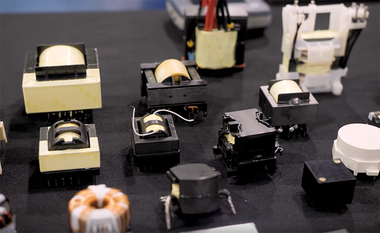
A transformer is simply a pair of inductors that are wounded, such that they have maximum magnetic coupling between them. The transformers are used to step up or step down AC voltage/current. As electromagnetic induction happens only with fluctuating or alternating currents, transformers are also used for DC isolation of electronic circuits, where transformers only allow AC voltages to pass through one circuit to another. The transformers are also used for impedance matching between different circuits or a circuit with its load. These are also used for coupling balanced and unbalanced circuits, loads, and feedback systems.
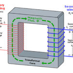
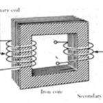
The coil or inductor in which the source current is passed is called primary winding, or simply primary. The coil or inductor in which the current is induced is called secondary winding, or simply secondary. A step-up transformer has a higher secondary voltage than its primary voltage. A step-down transformer has a lower secondary voltage than its primary voltage. As in an ideal transformer, electrical power should be conserved (per the law of conservation of energy), in a step-up transformer secondary current is lower than the primary current and in a step-down transformer secondary current is higher than primary current.
Coefficient of coupling
The quantity of total magnetic flux linked to another coil compared to total magnetic flux in a coil is known as the coefficient of coupling. It is defined as the ratio of the number of magnetic flux lines common between two coils (inductors) to the number of magnetic flux lines in a coil. The coefficient of coupling is denoted by the letter ‘K.’ Its value can be anywhere between 0 and 1. If two coils are perfectly magnetically coupled, their coefficient of coupling will be 1. If two coils are perfectly shielded from each other, their coefficient of coupling will be 0. So, the coefficient of coupling is a way to quantize magnetic coupling between two coils. In an ideal transformer, the coefficient of coupling between primary and secondary coils should be 1. That is, they should be perfectly magnetically coupled. The better the coils are magnetically coupled, the more efficient will be the electromagnetic induction between them.
Turn ratio
Turn ratio of a transformer is the ratio of the number of turns in the primary to the number of turns in the secondary. This ratio plays an important role in determining the induced voltage and current in the secondary winding from the primary. The following equation gives the turn ratio:
Turn Ratio = NP/Ns
Where,
NP = Number of turns in primary coil
NS = Number of turns in secondary coil
Voltage ratio
The voltage ratio of a transformer is the ratio of the voltage induced in secondary coil to the voltage of the primary. The following equation gives the voltage induced in the secondary coil:
VS = NS dΦM/dt
Where,
VS = Voltage induced in the secondary coil
NS = Number of turns in the secondary coil
ΦM = Magnetic flux induced in the secondary coil
dΦM/dt = Rate of change of magnetic flux in the secondary coil
The following equation gives the magnetic flux induced in the secondary coil:
ΦM = ∫(VP/NP).dt
Where,
VP = Voltage of primary coil
NP = Number of turns in the primary coil
If we assume that there is perfect magnetic coupling between the primary and secondary coil, then the coefficient of coupling will be 1. Then, on differentiating the equation for magnetic flux in the secondary coil, we get the following equation:
dΦM/dt = d(∫(VP/NP).dt)/dt
= VP/NP
On substituting the above equation, we get:
VS = NS* VP/NP
Therefore,
VS/VP = NS/NP
As you can see, the induced voltage in the secondary coil relative to the voltage in the primary coil is directly related to the turn ratio of the transformer. If the secondary coil has more turns than the primary, then the secondary voltage will be greater than the primary voltage by the same ratio. Such a transformer will step up the AC voltage. If the secondary coil has a fewer number of turns compared to primary, the secondary voltage will be less than the primary voltage by the same ratio. Such a transformer will step down the AC voltage.
Therefore, just by ensuring a perfect magnetic coupling between two inductors, AC voltages can be precisely stepped up or down by just winding primary and secondary coils to a predetermined ratio of the number of turns.
Current ratio
As the voltage ratio of a transformer is related to its turn ratio, the current ratio can also be determined in terms of turn ratio. If we assume that it is an ideal transformer made up of ideal inductors magnetically coupled by a coupling coefficient of 1, the transformer should have no internal losses. Then according to the law of conservation of energy, the power induced in the secondary coil should be equal to power supplied to the primary.
PS = PP
Where,
PS = Electrical power induced in the secondary coil
PP = Electrical power supplied to the primary coil that is transferred to secondary coil as it is, due to perfect magnetic coupling
Therefore,
ISVS = IPVP
IS/IP = VP/VS
IS/IP = NP/NS
Where,
IS = current in secondary coil
IP = current in primary coil
We can see that the current ratio of an ideal transformer is equal to its turn ratio, while its voltage ratio is equal to the inverse of its turn ratio. Remember that these equations are derived on the condition that the primary and secondary coils of the transformer are ideal inductors, i.e. they do not have any operating losses, and there is a perfect magnetic coupling between the primary and secondary coil. In such a case, when there is no load circuit attached to the secondary coil, the transformer must behave like an ideal inductor, and current in the primary coil should be 90 degrees out of phase with the primary voltage.
Efficiency factor of transformer
Efficiency Factor of a transformer is defined as the percentage ratio of the electrical power induced in secondary coil to the electrical power supplied to the primary coil, as you can see in the following equation:
Efficiency Factor = (PS/PP)*100
In an ideal transformer, the efficiency factor should be 100 percent or power induced in the secondary coil should be equal to power supplied to the primary coil. In such a case, power supplied to the primary coil must be transferred to the secondary coil as it is without any operating losses. This is only possible when there is perfect magnetic coupling between primary and secondary, and both primary and secondary coils are ideal inductors, i.e. these have purely inductive impedance.
Practically, there are resistive losses in inductor coils and operating losses due to hysteresis and eddy currents in the inductor core. Also, it is not possible to achieve a coefficient of coupling between the coils that is exactly 1. That is why the power induced in the secondary coil is always less than the power supplied to the primary coil. So, the efficiency factor is always less than 100 percent. Power transformers have an efficiency factor between 80 percent and 90 percent. Most of the other transformers have a much smaller efficiency ratio. Even if a purely reactive load is connected at the secondary, there will be operating losses in the transformer due to resistive losses in coils. Practically, it is not either feasible or economical to design highly efficient transformers. Still, manufacturers try their best to achieve the maximum efficiency factor.
Impedance transfer ratio
Impedance is the effective resistance of a circuit or component to the alternating current combining the ohmic resistance and reactance. The impedance transfer ratio of a transformer is defined as the ratio of the impedance of the primary coil to the impedance of the secondary coil. It is an important factor when a transformer is used for coupling AC circuits. It is given by the following equation:
Impedance Transfer Ratio = ZP/ZS
= (VP/IP)/(VS/IS)
= (VP/VS)*(IS/IP)
= (NP/NS)2
If the impedance of the load at the secondary coil increases or decreases, the impedance at the primary coil also increases or decreases proportionally to the square of turn ratio and vice-versa. Therefore, by using a transformer of a given turn ratio for coupling two AC circuits, the impedance of two circuits can be matched. Suppose a circuit requires specific load impedance for it to proper function but its actual impedance may be different than the power source due to operating losses. Then, a transformer of suitable turn ratio can be used to couple the power source and the circuit to match their actual impedances. This is called impedance matching.
Phase relation in transformer
The voltage in the secondary coil is either in phase or out of phase by 180 degrees from the voltage in the primary coil depending upon the direction of the secondary coil winding or the way secondary coil winding is referenced in a circuit. If the secondary coil is wound in a direction and referenced such that current in it flows in the opposite direction to the direction of current in the primary, then the primary voltage and secondary voltage are in-phase, i.e. they do not have any phase difference.
For example, if the current flows in a clockwise direction in the primary coil and the secondary coil is wound and referenced such that induced current flows in the secondary coil in a counter-clockwise direction, then the primary and secondary voltages will be in in-phase. Similarly, if current flows in a counterclockwise direction in the primary coil and the secondary coil is wound and referenced such that induced current flows in the secondary coil in a clockwise direction, then also, the primary and secondary voltages will be in in-phase.
If the secondary coil is wound and referenced such that current in both primary and secondary flows in the same direction, then the primary and secondary voltages will be out of phase by 180 degrees. For example, if the secondary coil is wound and referenced such that in both primary and secondary coils, current flows in a clockwise or counterclockwise direction, the primary and secondary voltages will be out of phase by 180 degrees. It should be noted that the phase difference between current and voltage in secondary will be maintained as it is as the phase difference between current and voltage in the primary coil.
Reactance
If two AC circuits connected through a Transformer have no reactance (they are purely resistive), it is easy to match their impedance by selecting a suitable turn ratio. However, when the circuits have some reactance, the impedance becomes a function of signal frequency, and the two circuits cannot be exactly impedance matched. Therefore, whenever AC circuits with some reactance are coupled through a transformer, it is important to cancel their reactance. As inductive and capacitive reactance are opposite to each other, inductive reactance of a circuit can be canceled by connecting a suitable capacitor in its series before connecting it to the transformer.
Similarly, if a circuit has capacitive reactance, it can be canceled by connecting a suitable inductor in its series before connecting it to the transformer. Some small amount of reactance can be tolerated at low-frequency circuits. However, at high-frequency radio circuits, impedance matching should be almost perfect. It is possible to achieve nearly perfect impedance matching by using reactance canceling networks on both sides and using adjustable impedance matching.
Center tap transformers
Any transformer is essentially a two-port device with at least four terminals. However, most of the commercial transformers have center taps. The center taps are the electrical connections made between the ends of the winding. These can be on either or both primary and secondary winding. The center taps divide the number of turns of a winding by integral factors and allow obtaining voltages in sub-divisions of the maximum output voltage. For example, if a center tap divides secondary winding into two halves, half of the output voltage can be drawn between one end and the center tap of the winding. If the center tap is used as ground, symmetrical voltages can be drawn between the center tap and other ends of the winding. Similarly, the supply voltage can also be divided by providing center taps at the primary winding.
Non-ideal electrical properties of transformers
Like any other electrical and electronic component, transformers are also just not perfect. Several non-ideal characteristics are experienced with the transformers. Some of the most critical, non-ideal characteristics are the following:
Leakage Flux – There is never perfect coupling between primary and secondary coils. It is not actually possible to achieve a coefficient of coupling that may be exactly 1. The magnetic flux that is not common to both windings is called leakage flux. Due to leakage flux, self-induction occurs in the primary coil, and some inductive voltage opposing the supply voltage is induced on the primary coil.
Leakage Reactance – There is some small amount of leakage inductance in both windings. This inductance causes some reactance on both coils, which is called leakage reactance. The leakage reactance acts as unwanted inductances connected in series to transformer coils. Due to these leakage inductances, there is some voltage drop on both coils. The voltage drop increases as the current through the transformer coils is increased, and more power is drawn at the secondary.
Coil Resistance – The coils have some resistance, which serves as the internal resistance of the transformer. These internal resistances appear at both coils and act as series resistance to transformer coils. Due to internal resistances, there is a secondary voltage drop on both coils.
Stray Capacitance – Stray capacitance appears on transformer coils due to slightly different voltage levels of coil turns. These capacitances appear on both coils and are modeled as parallel capacitors to coils. At low frequencies, stray capacitance does not have any significant effect, but at high frequencies, this capacitance can resonate with leakage inductance. This changes the expected behavior of the transformer near the resonant frequency.
Mutual Capacitance – There is also some capacitance between the two transformer coils. This is modeled as a mutual capacitance connected between transformer coils. There is also some mutual capacitance between the coils and the core, coils and the shield, and coils and the chassis.
Core Losses – There are internal (power) losses due to eddy currents and hysteresis in the transformer core. To minimize these losses, the core is often laminated into sheets so that that circular eddy currents could be avoided.
Can we use a step-down transformer to step up?
The ratio of the number of turns of primary and secondary coils make a transformer step-up or step-down. So, can we not use a step-down transformer to step up AC voltages by just reversing the connections or vice-versa. That seems obvious, but it’s not feasible. The secondary winding of transformers is designed to have low impedance. This is done to maximize the efficiency factor of the transformer and minimize operating losses. If the connections are reversed to use secondary winding as primary winding, a large surge current will flow through it, which can permanently damage the transformer or cause a short circuit.
Secondly, both windings have their respective voltage ratings. In an attempt to use a step-down transformer as step-up or vice-versa, the voltage rating of the other winding will be dangerously exceeded. This can even cause the transformer to burn or explode.
So, while using a transformer, it is essential to take care of the following issues –
- Always use primary winding as primary and secondary winding as secondary. It is not feasible to reverse connections to use step-up as a step-down transformer or vice-versa due to different impedance ratings of the two coils.
- Never exceed the voltage ratings of the transformer coils. Any excess voltage can cause permanent damage to coils or the core of the transformer. The transformer can even burn or explode on the application of an excessive voltage at either side.
- There should be no significant DC current applied to transformer coils. This can cause a short circuit or can permanently damage or burn the transformer.
- The transformer should always be operated at the specified frequency. On operating the transformer at lower frequencies can cause surge currents in the primary. This can cause the coils or core to burn or may lead to a short circuit. Operating a transformer at a frequency lower than the specified one has similar effects as applying DC current to the primary coil of the transformer.
In the next article, we will discuss different types of transformers. The transformers are classified by the shapes and designs of the core as well as by their applications. In the next article, we will also discuss different types of cores used in transformers.
You may also like:
Filed Under: Tutorials




Questions related to this article?
👉Ask and discuss on Electro-Tech-Online.com and EDAboard.com forums.
Tell Us What You Think!!
You must be logged in to post a comment.