Engineers Garage

  • Electronics Projects and Tutorials
    • Electronic Projects
      • Arduino Projects
      • AVR
      • Raspberry pi
      • ESP8266
      • BeagleBone
      • 8051 Microcontroller
      • ARM
      • PIC Microcontroller
      • STM32
    • Tutorials
      • Audio Electronics
      • Battery Management
      • Brainwave
      • Electric Vehicles
      • EMI/EMC/RFI
      • Hardware Filters
      • IoT tutorials
      • Power Tutorials
      • Python
      • Sensors
      • USB
      • VHDL
    • Circuit Design
    • Project Videos
    • Components
  • Articles
    • Tech Articles
    • Insight
    • Invention Stories
    • How to
    • What Is
  • News
    • Electronic Product News
    • Business News
    • Company/Start-up News
    • DIY Reviews
    • Guest Post
  • Forums
    • EDABoard.com
    • Electro-Tech-Online
    • EG Forum Archive
  • DigiKey Store
    • Cables, Wires
    • Connectors, Interconnect
    • Discrete
    • Electromechanical
    • Embedded Computers
    • Enclosures, Hardware, Office
    • Integrated Circuits (ICs)
    • Isolators
    • LED/Optoelectronics
    • Passive
    • Power, Circuit Protection
    • Programmers
    • RF, Wireless
    • Semiconductors
    • Sensors, Transducers
    • Test Products
    • Tools
  • Learn
    • eBooks/Tech Tips
    • Design Guides
    • Learning Center
    • Tech Toolboxes
    • Webinars & Digital Events
  • Resources
    • Digital Issues
    • EE Training Days
    • LEAP Awards
    • Podcasts
    • Webinars / Digital Events
    • White Papers
    • Engineering Diversity & Inclusion
    • DesignFast
  • Guest Post Guidelines
  • Advertise
  • Subscribe

Designing 250 Milli Watt Audio Power Amplifier – 2/9

By Dikhsa April 17, 2025

In the previous tutorial, basics of audio amplifiers were discussed. It has been already mentioned that on the basis of application, there are two types of audio amplifiers – 
1) Pre-Amplifier
2) Power Amplifier
The pre-amplifiers are used to level up the audio signals from a microphone or audio source to standard voltage levels while the power amplifiers are generally used at the output stage of the audio systems to boost audio signals before they are reproduced by the speakers. In this tutorial, a power amplifier with 250 Milli-Watt output power will be designed. The audio amplifier designed in this project will operate in range from 20 Hz to 20 KHz which is the same as of the audible range of frequencies by humans. The amplifier circuit will be designed to have a variable voltage gain in range from 26 dB to 46 dB. 
The circuit of this amplifier uses operational amplifier as the building block. So, the LM-386 IC is the heart of the circuit. LM-386 is a low power audio power amplifier IC. The amplifier circuit will be equipped with volume control feature by using a variable resistor at the output.   
In the previous tutorial, various design parameters associated with the audio amplifiers were discussed like Gain, Volume, Skew Rate, Linearity, Bandwidth, Clipping effect, Stability, Efficiency, SNR, Output power, THD and loop grounding. This amplifier circuit will be designed considering the following design parameters – 
Gain (Voltage) – 26 dB to 46 dB
Bandwidth – 20 Hz to 20 KHz
Output Power – 250 mW
The amplifier will be designed to feed a 250 mW speaker having an impedance of 8 ohms. The circuit will have the following additional features – 
– No Clipping Effect
– Volume Control
The designing of the circuit will be followed by testing of the circuit for the verification of the intended design factors and the observation of the output waveform on a CRO to check out for the clipping effect. 
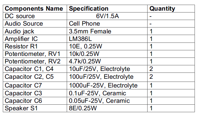
Components Required – 
List of Components required for 250 Milli Watt Audio Power Amplifier
Fig. 1: List of Components required for 250 Milli Watt Audio Power Amplifier
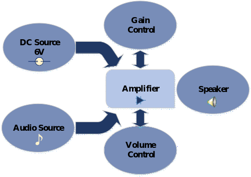
Block Diagram – 

Block Diagram of 250 Milli Watt Audio Power Amplifier

Fig. 2: Block Diagram of 250 Milli Watt Audio Power Amplifier

Circuit Connections – 
The amplifier circuit is built by assembling the following components together – 
1) DC Source – A battery of 6V and 1.5 A rating is used to power the circuit. This DC source also provides the bias voltage to the amplifier. 
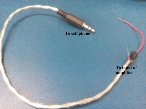
2) Audio Source – The audio input is provided from a smart phone. For receiving audio from the smart phone, an audio jack of 3.5 mm is plugged into the phone. The 3.5 mm audio jack has three wires – one for ground and two wires for left and right channel. As the amplifier is designed for single channel, only one of the channel wires will be connected to the amplifier as audio input. The ground wire of the jack will be connected to the common ground of the circuit. 
Typical Image of 3.5 MM Audio Jack
Fig. 3: Typical Image of 3.5 MM Audio Jack

3) LM386 Audio Power Amplifier – LM386 is a low voltage audio power amplifier IC. It operates between a voltage range of 4 V to 12 V. In this circuit, the IC is provided a bias voltage of 6 V. This IC can drive a load having impedance in range from 4 ohms to 32 ohms. As the speaker used as load at the output of the amplifier has 8 ohms impedance, the IC is suitable to drive it well. Internally, the voltage gain of the IC is set to 20 (26 dB) but it can be set between 20 (26 dB) to 200 (46 dB) by connecting a suitable combination of resistor and capacitor between its pins 1 and 8. The IC has 8 pins in PDIP package with the following pin configuration – 
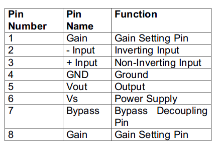
Table Listing Pin Configuration of LM386 Audio Power Amplifier IC
Fig. 4: Table listing pin configuration of LM386 Audio Power Amplifier IC 
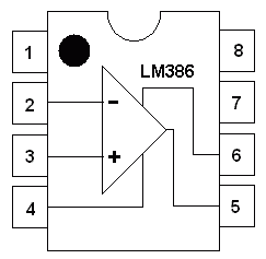
The IC has the following pin diagram – 
Pin Diagram of LM386 IC
Fig. 5: Pin Diagram of LM386 IC
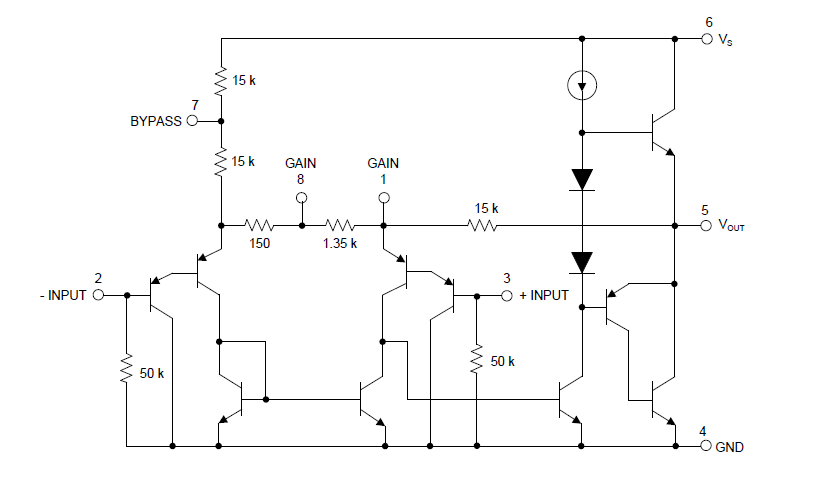
The IC has the following Internal Diagram – 

Internal Circuit Diagram of LM386 IC

Fig. 6: Internal Circuit Diagram of LM386 IC

Its internal circuitry can be represented by the following functional diagram – 
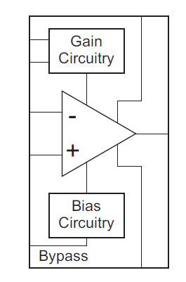
Functional Diagram of LM386 IC

Fig. 7: Functional Diagram of LM386 IC

This IC is basically an operational amplifier whose voltage gain can be adjusted by using a proper RC circuit between its gain setting pins. If the gain setting pins are left open, the voltage gain of the amplifier is internally set to 20 (26 dB). For adjusting the gain between the desired range of 20 (26 dB) and 200 (46 dB), a variable resistor (Shown as RV2 in the circuit diagram) of 4.7 Kilo ohms and a capacitor (Shown as C1 in the circuit diagram) of 10 uF are connected between the pins 1 and 8 of the IC.  For controlling the output volume level, a variable resistor (Shown as RV1 in the circuit diagram) is connected at the input of the non-inverting pin. This variable resistor actually changes the amplitude (input voltage level) of the input signal as amplitude defines the loudness of the audio signal. 
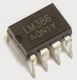
Typical Image of LM386 IC

Fig. 8: Typical Image of LM386 IC

The Pin 2 and 3 are the Input pins of IC. The pin 2 is the inverting input pin and it is grounded. The pin 3 is the non-inverting input pin and is used for feeding the audio signal which is to be amplified along with a 10k potentiometer and a capacitor which blocks any DC signal from the input. The pin 4 is the ground pin and is connected to the common ground. The pin 6 is the Power supply pin of IC and it is connected to 6V DC. A filter capacitor (Shown as C2 in the circuit diagram) of 100 uF is used removing any high-frequency ripples at the input. At the pin 5 which is the output pin of the IC, a capacitor (Shown as C7 in the circuit diagram) of 1000 uF is connected to block any DC components. The DC components (as are appeared in case of clipping effect) can damage the speaker connected at the output of the circuit. 
Along with this capacitor, an RC filter circuit consisting of a resistor (Shown as R1 in the circuit diagram) of 10 ohms and a capacitor (Shown as C6 in the circuit diagram) of 0.05 uF is used at the output pin. This is called a ‘Zobel network’. It ensures the impedance of speaker appears as a steady resistance for the amplifier after output. So it helps in stabilizing the frequency and oscillations at the output. If the capacitor C6 and resistor R1 are interchanged then it would be no longer a Zobel network but still, the output impedance will remain constant. The pin 7 which is the Bypass Terminal pin is grounded with a capacitor for improving the stability of the amplifier output.
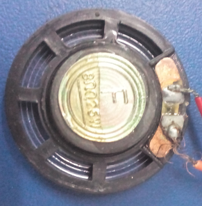
4) Speakers – A speaker of 250 mW power rating  and 8 ohms impedance is used as load at the output of the amplifier. The speaker is connected at pin 5 of the IC which is the output pin of the LM386 and the ground wire of the speaker is connected to the common ground. 
Typical Image of 250 mW 8 Ohms Speaker
Fig. 9: Typical Image of 250 mW 8 Ohms Speaker

While assembling this circuit following precautions must be taken care of – 
1. Always use the filtering capacitor at the input terminal of power supply to avoid the unwanted ripples.
2. Use the speaker of equivalent or high power rating as amplifier output power.
3. Always use a series capacitor at the output of the amplifier to block any DC component.
4. Use Zobel network for frequency stability.
5. Always calculate the maximum power rating of the amplifier before connecting it to the speaker. The practical value may differ from theoretical one. 
6. For better stability ground the bypass pin using a capacitor. 
7. Always check the power rating of LM386 IC in its datasheet, as different companies have different ratings. 
8. Avoid clipping of the output signal as it may damage the speaker.  
9. Always place the components as close as possible to  reduce the noise in  the circuit
10. Always follow star topology when grounding, this will keep the noise low and reduce the problem of loop grounding. 
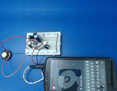
Prototype of 250 mW Audio Power Amplifier
Fig. 10: Prototype of 250 mW Audio Power Amplifier 

How the circuit works – 

The LM386 is basically an operational amplifier. The IC comes with an internal gain circuitry which has an internal resistor of 1.35 kilo ohms setting the default gain of the amplifier to 20 (26 dB). The internal resistor can be bypassed by connecting a capacitor between pins 1 and 8 of the IC. On bypassing the internal resistor, the gain is set to 200 (46 dB). The voltage gain of the amplifier can be adjusted between 20 (26 dB) and 200 (46 dB) by connecting a variable resistor in series with the bypassing capacitor. 
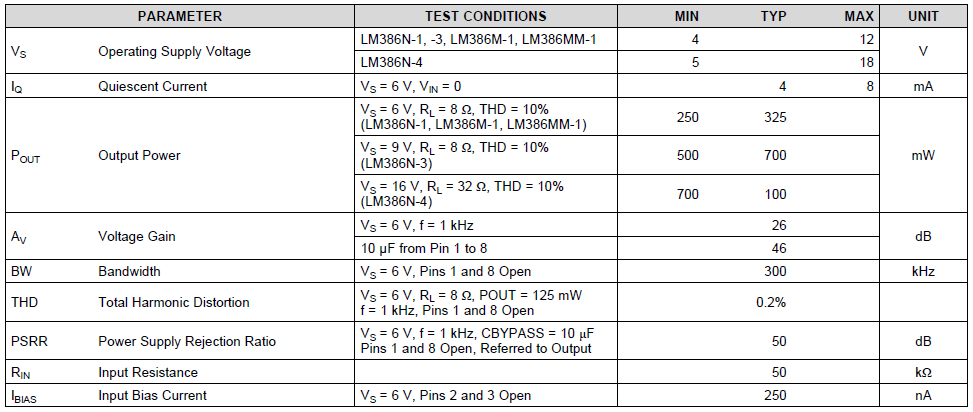
The output power of LM386 varies as per the DC input voltage or bias voltage. According to the datasheet, the LM386N-1 has the following output power for a 6V supply voltage and 8 ohms load –  
At 6V/8E – 250 mW (min) to 325 mW (typical)
Table Listing Electrical Characterstics of LM386 IC
Fig. 11: Table listing electrical characterstics of LM386 IC

So, with a supply voltage set to 6V and a load of 8 ohms at the output, the  power output of the amplifier can range from 250 mW to 325 mW. Considering minimum power output from the amplifier IC 250 mW and load impedance (purely resistive and independent of frequency) being 8 ohms, the Root Mean Square Voltage at the output of the amplifier can be calculated as follow – 
Po= (Vrms)2/R
Where, 
Output Power, Po = 250 mW
Load Resistance, R = 8 ohms 
On putting the values, 
0.25 = (Vrms)2/8
RMS (Root Mean Square) Voltage, Vrms = 1.4 V
So, the peak to peak voltage for 250 mW power is as follow – 
Vp-p = Vrms*(2)1/2
Vp-p = 1.4*1.414
Vp-p(maximum)= 2V (approx.)
The maximum current delivered by the IC for 250 mW power output can be calculated as follow –  
Po = Vrms*Io
0.25 = 1.4*Io
Io = 178mA
Maximum Output current, Io = 178 mA (approx.)
The input voltage at 26 dB gain for output Peak to Peak voltage being 2V can be calculated as follow – 
Gain = 26 db/20
Gain = Output voltage(peak – peak) / Input voltage(peak-peak)
Input voltage = 2/20
Input voltage, Vin (p-p) = 100mV
The input voltage at 46 dB gain for output Peak to Peak voltage being 2V can be calculated as follow – 
Gain = 46 db/200
Gain = Output voltage(peak – peak) / Input voltage(peak-peak)
Input voltage = 2/200
Input voltage, Vin (p-p) = 10 mV
So, on applying an input voltage in range from 10 mV to 100 mV, the LM386 providing a voltage gain between 20 (26 dB) and 200 (46 dB), the output voltage about 2V must be obtained. So, the amplitude of the input signal can range from 10 mV to 100 mV without clipping. 
Considering maximum power output from the amplifier IC being 325 mW and load impedance (purely resistive and independent of frequency) being 8 ohms, the Root Mean Square Voltage at the output of the amplifier can be calculated as follow – 
Po= (Vrms)2/R
Where, 
Output Power, Po = 325 mW
Load Resistance, R = 8 ohms 
On putting the values, 
0.325 = (Vrms)2/8
RMS (Root Mean Square) Voltage, Vrms = 1.6 V
So, the peak to peak voltage for 325 mW power is as follow – 
Vp-p = Vrms*(2)1/2
Vp-p = 1.6*1.414
Vp-p(maximum)= 2.26 V (approx.)
The maximum current delivered by the IC for 325 mW power output can be calculated as follow –  
Po = Vrms*Io
0.325 = 1.6*Io
Io = 203 mA
Maximum Output current, Io = 203 mA (approx.)
The input voltage at 26 dB gain for output Peak to Peak voltage being 2.26 V can be calculated as follow – 
Gain = 26 db/20
Gain = Output voltage(peak – peak) / Input voltage(peak-peak)
Input voltage = 2/20
Input voltage, Vin (p-p) = 113 mV
The input voltage at 46 dB gain for output Peak to Peak voltage being 2.26 V can be calculated as follow – 
Gain = 46 db/200
Gain = Output voltage(peak – peak) / Input voltage(peak-peak)
Input voltage = 2.26/200
Input voltage, Vin (p-p) = 11 mV
So, on applying an input voltage in range from 11 mV to 113 mV, the LM386 providing a voltage gain between 20 (26 dB) and 200 (46 dB), the output voltage about 2.26 V must be obtained. So, the amplitude of the input signal for typical power output of the IC can range from 11 mV to 113 mV without clipping. 
Assuming that the IC delivers minimum power as per its datasheet, the input audio signal having amplitude in range from 10 mV to 100 mV with about 10 percent tolerance can be applied at the input of the amplifier. The input signal must be amplified from 20 times to 200 times depending upon the gain set by the variable resistor at pin 8 of the IC. 
Testing the circuit – 
For the testing of the amplifier circuit, the function generator is used as the input source. The function generator is used to generate a sine wave of constant amplitude and frequency. Any audio signal is also basically a sine wave so a function generator can be used instead of using a microphone or actual audio source. So, the function generator can be used as input source for testing the audio amplifier circuit. During testing, at the output also, a speaker is not used as a load as the speaker is resistive as well as inductive. At different frequencies, its inductance changes which in turn changes the impedance (R and L combination) of the speaker. So, the use of a speaker as load at the output of the amplifier for deriving its specifications may give false or non-standard results. In place of speaker, a dummy load which is purely resistive is used. As resistance does not change with frequency so it can be considered a reliable load independent of the frequency of the input audio signal. 
For testing of the amplifier circuit, first the input voltage is set between the applicable range between 10 mV and 100 mV. The frequency of the input signal is set to 1 KHz. Then, the output waveform is observed at CRO and the input signal is increased until the output waveform starts clipping. The Peak to Peak output voltage just before clipping is measured for circuit analysis like determining the output power and gain of the amplifier. 
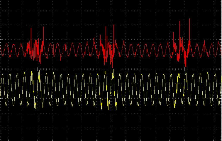
At 20 dB gain the following input and output waveforms were observed where input signal is represented by red waveform and the output signal is represented by the yellow waveform – 
Graph of Output from LM-386 Audio Power Amplifier as observed on CRO
Fig. 12: Graph of output from LM-386 Audio Power Amplifier as observed on CRO
The output waveform was observed to start clipping at 2V level. However, the load impedance was practically found to be 10 ohms instead of 8 ohms. For this impedance the power drawn by the load can be calculated as follow – 
 Maximum Output power, Po = V2(p-p)/2R
Po = (2*2)/(2*10)
Po = 200 mW
So, with the increased impedance of the load, the output power of the amplifier was reduced to 200 mW from theoretical value of 250 mW. 
At 26 dB gain the following observations were taken – 
Table Listing Output Characterstics of LM-386 Audio Power Amplifier at 26 dB Gain
Fig. 13: Table listing output characterstics of LM-386 Audio Power Amplifier at 26 dB Gain
At 46 dB gain the following observations were taken – 
Table Listing Output Characterstics of LM-386 Audio Power Amplifier at 46 dB Gain
Fig. 14: Table listing output characterstics of LM-386 Audio Power Amplifier at 46 dB Gain
So, it can be observed that if the gain of the amplifier is set to 26 dB, the input voltage or amplitude of the input signal must not exceed 100 mV and if the gain of the amplifier is set to 46 dB, the input voltage or amplitude of the input signal must not exceed 10 mV as the output voltage from the power amplifier IC starts clipping at 2 V level.  
So, in this tutorial, an audio power amplifier having 250 mW power output (practically 200 mW power output due to actual load impedance being 10 ohms) having a gain in range from 26 dB to 46 dB is built. This amplifier circuit can be used in a TV sound system, radio amplifier or in portable audio players. The amplifier circuit designed in this tutorial is simple to construct and is small in size. It has a variable gain and volume control feature. 
In the next tutorial, 1 Watt Power Amplifier will be designed.

You may also like:


  • What are the top development boards for AI and ML?

  • What are top applications of CAN protocol?

  • What are LoRa gateways and what types are available?

  • What are the two types of hardware filters?

  • What are hardware filters and their types?

  • What are the different types of integrated circuits?

Project Video


Filed Under: Audio Electronics, Featured Contributions, Tutorials


Next Article

← Previous Article
Next Article →

Questions related to this article?
👉Ask and discuss on EDAboard.com and Electro-Tech-Online.com forums.


Tell Us What You Think!! Cancel reply

You must be logged in to post a comment.

EE TECH TOOLBOX

“ee
Tech Toolbox: Internet of Things
Explore practical strategies for minimizing attack surfaces, managing memory efficiently, and securing firmware. Download now to ensure your IoT implementations remain secure, efficient, and future-ready.

EE Learning Center

EE Learning Center
“engineers
EXPAND YOUR KNOWLEDGE AND STAY CONNECTED
Get the latest info on technologies, tools and strategies for EE professionals.

HAVE A QUESTION?

Have a technical question about an article or other engineering questions? Check out our engineering forums EDABoard.com and Electro-Tech-Online.com where you can get those questions asked and answered by your peers!


RSS EDABOARD.com Discussions

  • SPI speed pic18f66j15
  • GanFet power switch starts burning after 20 sec
  • RF-DC rectifier impedance matching
  • Inverting OpAmp - basic circuit question
  • 12VAC to 12VDC 5A on 250ft 12AWG

RSS Electro-Tech-Online.com Discussions

  • LED circuit for 1/6 scale diorama
  • stud mount Schottky diodes
  • Hi Guys
  • using a RTC in SF basic
  • Can I use this charger in every country?

Featured – Designing of Audio Amplifiers part 9 series

  • Basics of Audio Amplifier – 1/9
  • Designing 250 Milli Watt Audio Power Amplifier – 2/9
  • Designing 1 Watt Audio Power Amplifier – 3/9
  • Designing a Bass Boost Amplifier – 4/9
  • Designing a 6 Watt Car Audio Amplifier – 5/9
  • Design a low power amplifier for headphones- 6/9

Recent Articles

  • Fischer connector system adds ratchet locking system designed for 300g shock resistance
  • Littelfuse introduces tactile switch with enhanced bracket peg design for mounting strength
  • Infineon releases GaN switch with monolithic bidirectional design
  • Sienna Semiconductor data converters feature sample rates from 20 to 250 Msps
  • Delta’s 5,500 W power supplies achieve 97.5% energy efficiency for AI servers

EE ENGINEERING TRAINING DAYS

engineering

Submit a Guest Post

submit a guest post
Engineers Garage
  • Analog IC TIps
  • Connector Tips
  • Battery Power Tips
  • DesignFast
  • EDABoard Forums
  • EE World Online
  • Electro-Tech-Online Forums
  • EV Engineering
  • Microcontroller Tips
  • Power Electronic Tips
  • Sensor Tips
  • Test and Measurement Tips
  • 5G Technology World
  • Subscribe to our newsletter
  • About Us
  • Contact Us
  • Advertise

Copyright © 2025 WTWH Media LLC. All Rights Reserved. The material on this site may not be reproduced, distributed, transmitted, cached or otherwise used, except with the prior written permission of WTWH Media
Privacy Policy

Search Engineers Garage

  • Electronics Projects and Tutorials
    • Electronic Projects
      • Arduino Projects
      • AVR
      • Raspberry pi
      • ESP8266
      • BeagleBone
      • 8051 Microcontroller
      • ARM
      • PIC Microcontroller
      • STM32
    • Tutorials
      • Audio Electronics
      • Battery Management
      • Brainwave
      • Electric Vehicles
      • EMI/EMC/RFI
      • Hardware Filters
      • IoT tutorials
      • Power Tutorials
      • Python
      • Sensors
      • USB
      • VHDL
    • Circuit Design
    • Project Videos
    • Components
  • Articles
    • Tech Articles
    • Insight
    • Invention Stories
    • How to
    • What Is
  • News
    • Electronic Product News
    • Business News
    • Company/Start-up News
    • DIY Reviews
    • Guest Post
  • Forums
    • EDABoard.com
    • Electro-Tech-Online
    • EG Forum Archive
  • DigiKey Store
    • Cables, Wires
    • Connectors, Interconnect
    • Discrete
    • Electromechanical
    • Embedded Computers
    • Enclosures, Hardware, Office
    • Integrated Circuits (ICs)
    • Isolators
    • LED/Optoelectronics
    • Passive
    • Power, Circuit Protection
    • Programmers
    • RF, Wireless
    • Semiconductors
    • Sensors, Transducers
    • Test Products
    • Tools
  • Learn
    • eBooks/Tech Tips
    • Design Guides
    • Learning Center
    • Tech Toolboxes
    • Webinars & Digital Events
  • Resources
    • Digital Issues
    • EE Training Days
    • LEAP Awards
    • Podcasts
    • Webinars / Digital Events
    • White Papers
    • Engineering Diversity & Inclusion
    • DesignFast
  • Guest Post Guidelines
  • Advertise
  • Subscribe