What is Low pass circuit?
This is basically a low pass circuit which is used to separate out low frequency sounds from audio signals at audio play back devices. A simple loudspeaker is not capable of reproducing all the frequencies of the audible range. Different kinds of loudspeaker are available which can reproduce the sound at certain range of frequencies. Tweeters are the kind of loudspeakers which are used to reproduce high frequency audible sounds and woofers are the general term for the loudspeakers which are used only for reproducing low frequency sounds. In an audio playback device at least the low frequency signals are required to filter out, amplified and fed to the woofer and such kind of circuitry is called bass separator circuit.
Working of Bass Separator circuit:
This article discusses how to design a simplest active bass separator circuit with design details. The bass separator circuit alone is realized with the help of commonly available op-amp ICs. For demonstrating the working a bass beat is played in a mobile phone which is captured, amplified and mixed with a high frequency musical signal and is then again separated out using the bass separator circuit and reproduced in a loudspeaker.
DESCRIPTION
This circuit uses two stage amplifiers with a microphone to capture and amplify the bass beats played on an external device so that it should have enough loudness when mixing with other sounds. A music generator IC is used to produce high frequency musical sound which will be then mixed with the audio mixing circuit. The audio mixing circuit alone is a very simple summing amplifier made with an op-amp. The mixed signal is then applied to a Butterworth low pass filter to separate out the low frequency components and they are amplified with another op-amp based circuit before fed them to a loudspeaker.

Fig. 1: Block Diagram of Active Bass Separator
MICROPHONE COUPLER
The microphone coupler is a circuit which helps to couple out the weak audio signals generated at the microphone. This varying voltage is separated out from the DC voltage with the help of a coupling capacitor and fed to the following amplifier circuits.
With a condenser microphone a 10K resistor and a 0.1uF coupling capacitor is used in most of the circuits.

Fig. 2: Circuit Diagram of Microphone Coupler
TWO STAGE AMPLIFIER
Here a single transistor based amplifier circuit is used as the first stage amplifier for the audio signals coupled out from the microphone. This circuit is designed to have extremely high gain so that the audio signals are get amplified enough. The transistor is connected in a common emitter configuration and fixed bias technique is used for biasing the transistor.

Fig. 3: Circuit Diagram of First Stage Amplifier
The second stage amplifier is exactly similar in design with the first stage amplifier. This amplifier simply amplifies the signal more and at the output of this stage one can obtain a good enough voltage amplified signal which is ready to be current amplified by the following current amplifier circuit.

Fig. 4: Circuit Diagram of Second Stage Amplifier

Fig. 5: Circuit of Active Bass Separator on Breadboard
MUSIC GENERATOR
The music generated in this circuit with the help of a versatile musical IC UM66. This IC can works in the voltage range of 1.5V to 4.5V. The IC has three pins and the first pin is where the supply voltage is applied and the second pin is connected to the ground and the third pin produces a musical output signal.
Since the maximum voltage rating of the IC is only 4.5V, A 100 ohm resistor is connected between the first pin and the 5V power supply, which will produces a voltage drop when the current flows through it and hence maintain the voltage at the first pin at less than 4.5V.

Fig. 6: Circuit Diagram of Music Generator with IC UM66.

Fig. 7: Musical IC UM66 Circuit on BreadboardAmplifiers used in Circuit
SUMMING AMPLIFIER
The summing amplifier here is an op-amp based inverting amplifier designed to be having unity gain. This amplifier circuit has the feature of adding the different voltages applied at its inverting pin through separate equal valued input resistances connected at the inverting pin. A common 741 op-amp is used here as the summing amplifier of unity gain.

Fig. 8: Circuit Diagram of Summing Amplifier

Fig. 9: Circuit of Summing Amplifier on Breadboard
Suppose if S1 and S2 are the two signals applied at the input of the above circuit, then the output of the circuit will be;
S1 + S2
ACTIVE LOW PASS FILTER
The active low pass filter used for separating the low frequency signal here is a Butterworth filter. The Butterworth filter is a kind of filter which will provide equal gain for all the signals which falls under the pass band frequency of the filter. The common 741 op-amp is used here to realize the Butterworth low pass filter also.

Fig. 10: Circuit Diagram of Butterworth Low Pass Filter
The components R1, R2, C1 and C2 of the circuit determine the range of pass band frequencies with the following equations;
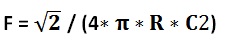 Where F is the cut-off frequency and, R = R1 = R2 and C2 = C1 / 2
The cut-off frequency is decided to be 500 Hz and the R is chosen as 2.2K. The values of the corresponding capacitors are calculated from the above equation as 0.2uF and 0.1uF for C1 and C2 respectively.
The filter circuits actually attenuate all the frequency and hence the output filtered low frequency signal need to be amplified by the following amplifier circuit.
AMPLIFIER
This is a simple inverting amplifier using an op-amp used to amplify the low amplitude filtered signals from the Butterworth filter. A common op-amp 741 is used as the inverting amplifier with a gain of about 10 dB.

Fig. 11: Circuit Diagram of Inverting Amplifier

Fig. 12: Inverting Amplifier Circuit on Breadboard
The gain of the circuit depends on the value of the resistors Rf and Ri as per the following equation;
G = – Rf / Ri
To obtain a gain of 10 dB the value of the Ri has been chosen as 1K and the Rf as 10K.
The 741 op-amp has an inbuilt current amplifying circuitry which helps to drive the loudspeaker directly with the low frequency bass beat signals.

Fig. 13: Circuit Diagram of Bass Separator with Amplifier, Active Low Pass Filter & Loudspeaker.

Fig. 14 : Bass Separator Circuit on Breadboard
Filed Under: Circuit Design, Featured Contributions
Log in to leave a comment:
Lost your password?
Don't have an account? Register here