The amplitude modulation is the simplest modulation technique among the wide verity of modulation techniques in use. In this technique the amplitude of a high frequency signal is varied corresponding to the variation in the amplitude of the low frequency modulating signal. The amplitude modulation of a high frequency signal is easy to achieve and the demodulation is also less complex compared to other techniques. The high frequency signal which is modulated to carry the low frequency audio signals are called ‘carrier frequency’ since they are used to carry the message signal to distant places with the help of wireless transmission devices. The audio signals used for modulation is called ‘modulating signal’ or ‘message signal’ or ‘base band signal’.
The demodulation of an AM wave can be done with only few components and unlike most of the demodulation technique there is no synchronization required between the modulator and demodulator circuits. The message signal appears as an envelope over the amplitude of the carrier wave and the demodulator make use of this to extract the modulating signal from the carrier and hence the technique of AM modulation is called envelope detection.
This article demonstrates how to generate an Amplitude Modulation (AM) and demodulate the same wave to get the original modulating wave. The AM wave is generated based on the circuits explained in article on AM modulation.
DESCRIPTION:
The AM demodulation is done using a low pass filter which can filter out the high frequency carrier from the AM wave in such a way that only the envelope of the carrier wave appears at the output of the filter. The amplitude of the filtered wave has variations corresponding to the amplitude of the modulating low frequency signal.
To get a better filtering using the Low pass filter the carrier frequency must be as large as possible and hence the carrier frequency generator circuit explained in the article AM modulation has to be modified for a very high frequency carrier signal. The only change that is required is the value of the capacitors C1 and C2 which determines the carrier frequency generation. The circuit used for generating the sine wave frequency is given below:
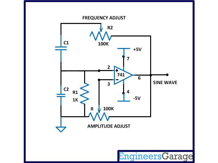
Fig. 1: Circuit Diagram Of Sine Wave Frequency Generator
The value of the resistance R, R1 and R2 are kept same as explained in the article AM modulation. Now the frequency can be calculated using the equation:
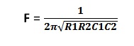
The value of R1 is kept the same as 1K but the value of the resistance R2 can be varied. As the value of the R2 decreases the output frequency of the circuit increases. As it is mentioned in the article AM modulation that the minimum value of the R2 which produces the highest stable frequency is around 130 ohms. In this project to increase the carrier frequency at least 10 times that achieved in the previous project the value of C1 and C2 is reduced to 10 times than that used in the previous AM modulation project. Hence the maximum carrier frequency can be calculated using the frequency equation as shown below:

The message frequency or modulating frequency generator circuit is kept the same as discussed in the article AM modulation. The following image shows the carrier wave and the message wave displayed in a dual-channel CRO.
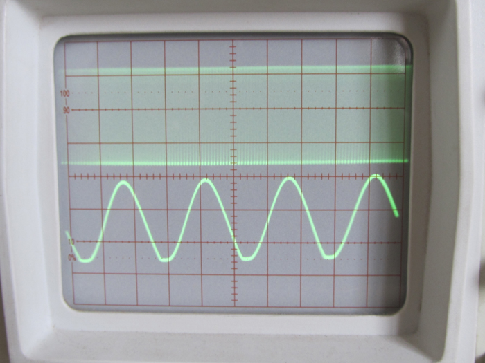
Fig. 2: Carrier Wave And Message Wave Displayed On CRO
The modulation is controlled in this project by some adjustment on the input potentiometer and also with the introduction of a 100K ohm resistor. The carrier signal is now fed through the N-channel from drain to source other than from the source to drain as in the previous project. The output can now be taken from the drain end of the FET where the internal channel modulation by the gate signal is more pronounced. The modified AM modulator circuit and the image of the circuit wired in the breadboard are shown below:

Fig. 3: Circuit Diagram Of Modified AM Modulator
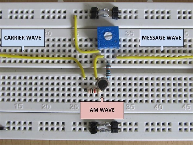
Fig. 4: Modified AM Modulator Circuit On Breadboard
The AM wave is displayed along with the original modulating wave using a dual channel CRO as shown in the following image:
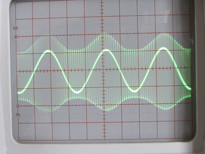
Fig. 5: AM Wave with Original Modulating Wave Displayed on CRO
The low frequency wave at the center is the message wave and the less bright high frequency wave is the modulated carrier wave. The amplitude of the message wave has been reduced significantly using the potentiometer R2 before applying to the FET so that it won’t over modulate the entire amplitude of carrier wave. The following image shows the waveform that appears at the input and output of the FET modulator.
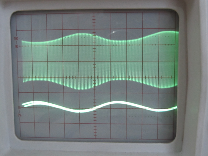
Fig. 6: Input And Output Waveform Of FET Modulator On CRO
Demodulation Steps
DEMODULATION STEPS
The demodulation of an AM wave is done using three basic steps which are listed below:
1) Rectification
2) Low pass filtering
3) Amplification
The AM wave in most of the cases will be a sine wave with both the half cycles and the Rectification is a process through which either one of the half cycles is eliminated so as to make the AC wave to a DC voltage with high frequency ripples and varying amplitude. The amplitude of the DC voltage still contains the variations which have been there in it before the rectification.
The high frequency ripples are eliminated using a filter circuit making the DC voltage smooth and continuous however maintaining the low frequency variations in the amplitude. The output of the filter circuit resembles the original modulating message wave. The demodulation is almost complete with the filter circuit but to use the demodulated signal for some useful purpose one more step has to be performed.
The output of the filter circuit is very small in amplitude and the noise will be so much that the Signal to Noise Ratio (SNR) is very low. To increase the amplitude of the demodulated signal and to improve the SNR, the amplification of the demodulated signal is necessary. The following section discusses the demodulation steps in detail.
Step:1 Rectification
In this project a simplest diode rectifier is used to rectify the AM wave. The circuit diagram used in this project and the image of the circuit wired in the bread board is shown in the following figure:
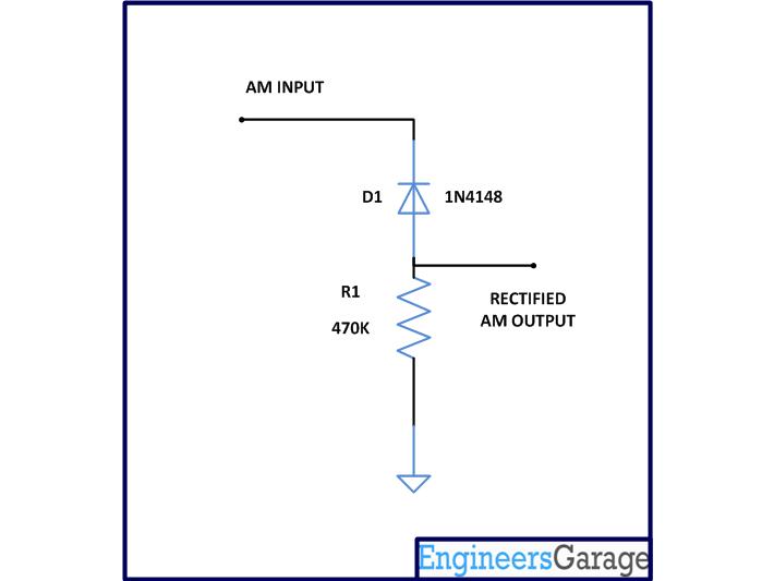
Fig. 7: Circuit Diagram Of Rectifier
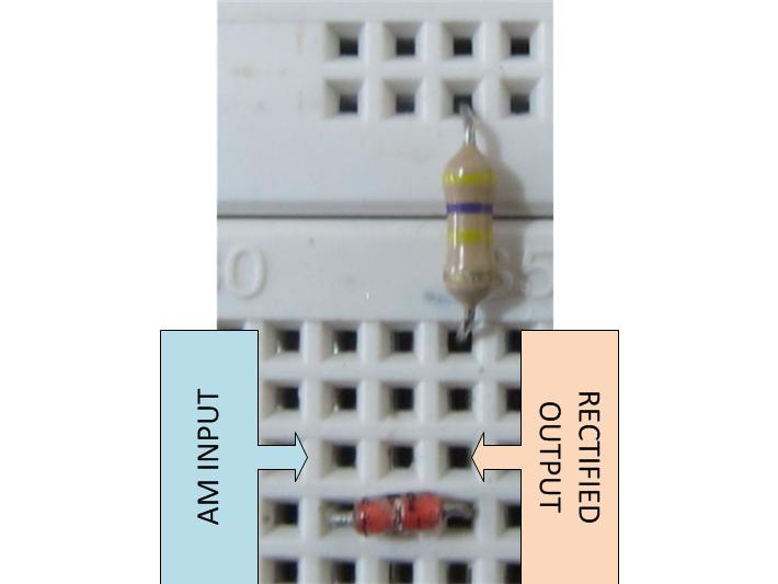
Fig. 8: Rectifier Circuit Wired On Breadboard
The circuit uses a germanium diode which has a cut in voltage of 0.3 volts which is less than that of the silicon diodes. The germanium diode 1N4148 has a very good high frequency response also when compared to the silicon diodes and hence perfect for the rectification of high frequency AM waves.
A high valued resistor of 470K is used to connect the diode to the ground of the circuit to complete the conduction path for the negative half cycles of the AM wave to ground, but without affecting the amplitude due to loading effect.
Simply the negative half cycles only flows through the diode and resistor and they can be taken out across the resistor. Thus the output of the rectifier circuit will be a DC voltage with amplitude varying high frequency ripples. The following image is the waveform at the output of the rectifier displayed in the CRO.
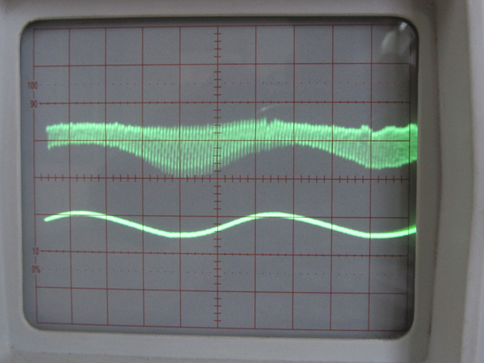
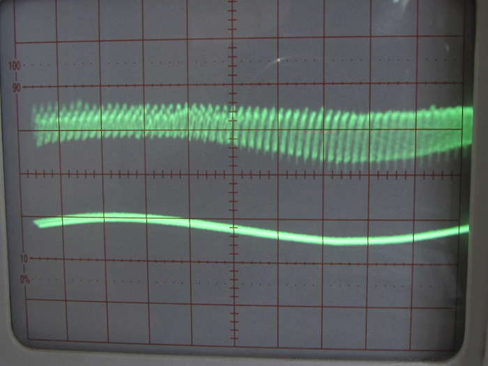
Fig. 9: Waveform Generated At Output Of Rectifier On CRO.
Step:2 Low pass filtering
A simple capacitor filter is used to filter out the low frequency amplitude variations from the rectified AM wave in the previous step. The capacitor allows only high frequency ripples to pass through it towards the ground and hence literally shorting them to the ground. The voltage appears across the capacitor will be the low frequency component of the rectified AM wave. Since this circuit filters out the low frequency component which appears like the envelope of the AM wave, this technique is called ‘envelope detection’
Demodulation contd.
The circuit diagram and the image of the circuit wired in the breadboard are shown in the following figure:
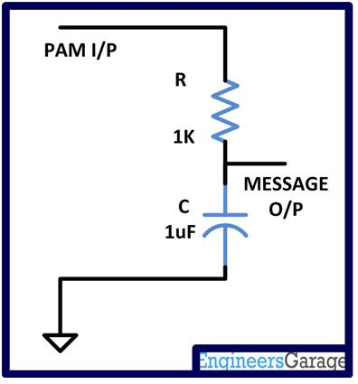
Fig. 10: Circuit Diagram Of Low Pass Filter
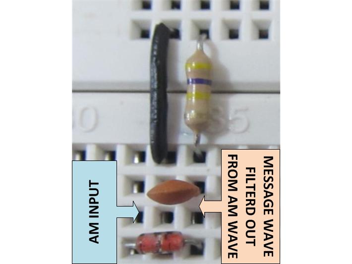
Fig. 11: Circuit Of Low Pass Filter On Breadboard
The capacitor used to short the high frequency carrier component through the ground is of the same value which has been used to generate the same frequency in the Wien bridge oscillator for the carrier frequency generation circuit. Any other capacitor will develop considerable impedance while the high frequency carrier component flows through it towards ground, and hence makes it impossible to eliminate the high frequency by shorting them to the ground.
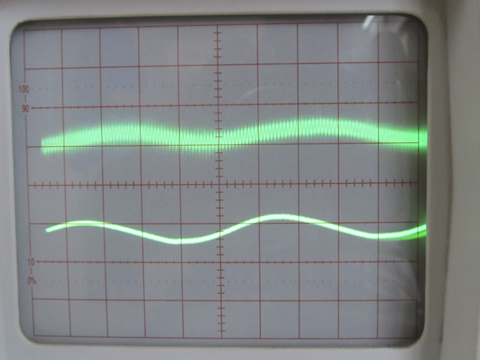
Fig. 12: Message Wave Of AM Modulation On CRO
The rectifier and the filter circuits form the actual demodulation circuitry for the AM modulated wave. So far the detection of the message wave is done but it needs to be amplified for better SNR and for an increased voltage so that it can be used with other circuits.
Step: 3 Amplification
In this project the amplification is done using a simple transistor based amplifier circuit. The NPN transistor in the circuit is wired in fixed bias common emitter configuration. The circuit used in this project along with the image of the circuit wired in the breadboard is shown below:
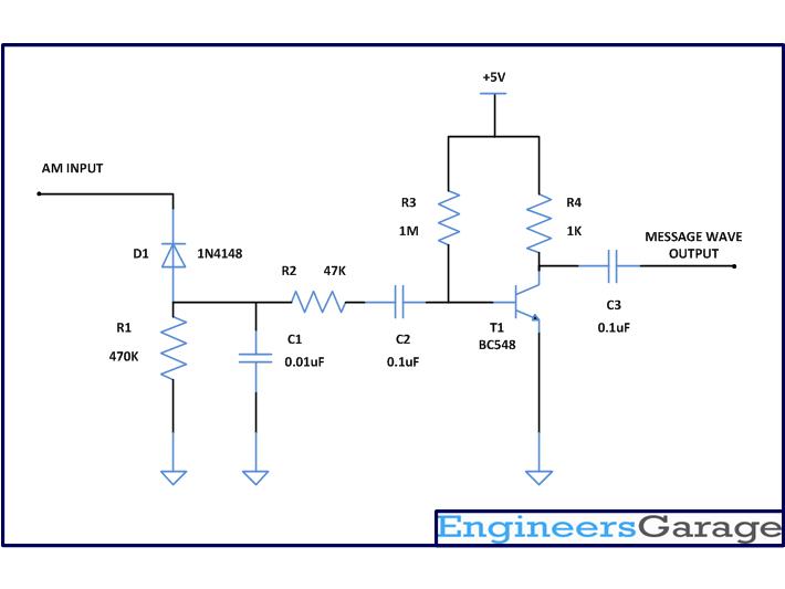
Fig. 13: Circuit Diagram Of Amplification With NPN Transistor
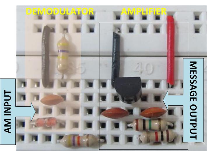
Fig. 14: Amplification Circuit With NPN Transistor On Breadboard
The Demodulator circuit is connected to an amplifier through a 47K ohm resistance so as to avoid the loading effect of the weak signal by the input of the amplifier circuit. This circuit uses a NPN transistor BC548 which has a very good current gain with a base current limiting resistor and a collector resistor. The base current limiting resistor is selected as high valued as possible since the transistor already has a higher current amplification factor (hfe). The amplified current flows through the collector resistor and develops a voltage drop which can then be coupled out using an output coupling capacitor. The input and the output coupling capacitors are used to allow only the varying component to flow in and out of the amplifier circuit. Note that the coupling capacitors are used here to couple only the message signal to the input and output of the transistor amplifier and hence their values are selected in same as those used in the message signal generating Wien bridge circuit discussed in the article AM modulation . One can use any other amplifier circuit or an external amplifier device to amplify the already detected message wave and hence this particular circuit dose not forms a part of standard AM demodulator circuit.
Note that the single stage transistor amplifier will introduce a 180 degree phase shift on the amplified output wave as shown in the following image of demodulated wave with the original message wave on a dual channel CRO.
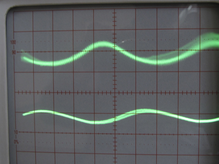
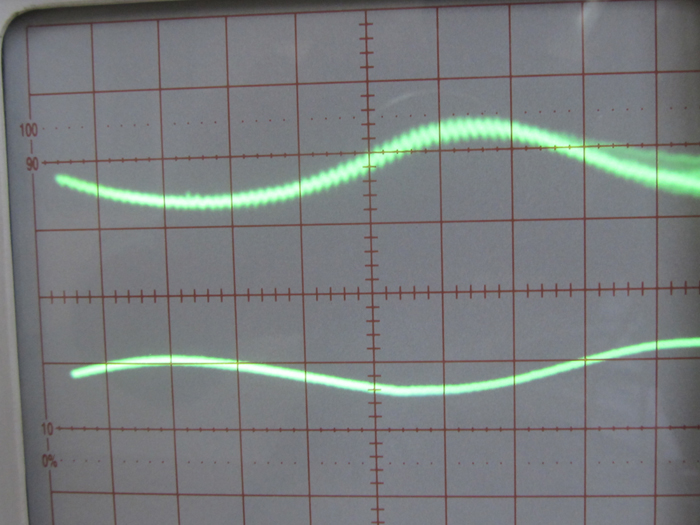
Fig. 15: Waveform Of Demodulation with original message wave On CRO
Filed Under: Circuit Design
Log in to leave a comment:
Lost your password?
Don't have an account? Register here