Variable resistor is a good choice to control motor speed. But if we want to insert some control logic(e.g changing motor rotation direction) or accurately control the motors rpm (resolutions per minute) then variable resistor technique can not full fill our requirement. To achieve the upper logic pwm(pulse width modulation) technique is best suited. In pulse width modulation input constant voltage to motor is divided in to sub cycles to reduce the amount of input voltage.
In this project our purpose is to control the speed of motor with stm32 microcontroller. Pwm technique is utilized in the project to control the motor speed and direction. St32f103c8t6 micorcontroller pre assembled board is used in the project. Stm32cubemx is used for stm32f103c8t6 microcontrollers gpio, timers configuration. Keil arm mdk 5 is used for writing and compiling the project code. Code is written by utilizing stm32 HAL libraries. If you are new and don’t know about stm32cubemx, keil arm mdk 5 and HAL libraries i advise you to first take the getting started tutorial with stm32cubemx and keil arm and HAL libraries. Just click the below button to take the tutorial.
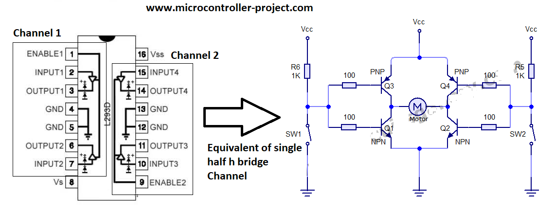
Transistor or Mosfet as external circuit to drive, control the speed and direction of DC motor
Half h bridge circuit for dc motor direction control
Project working
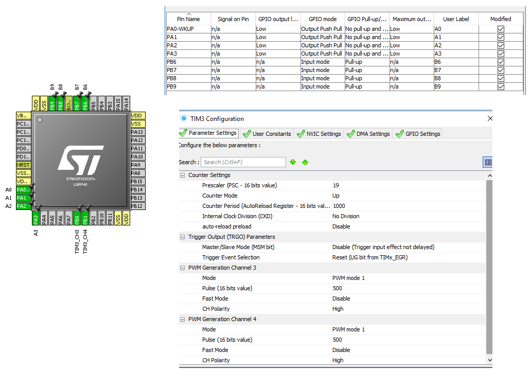
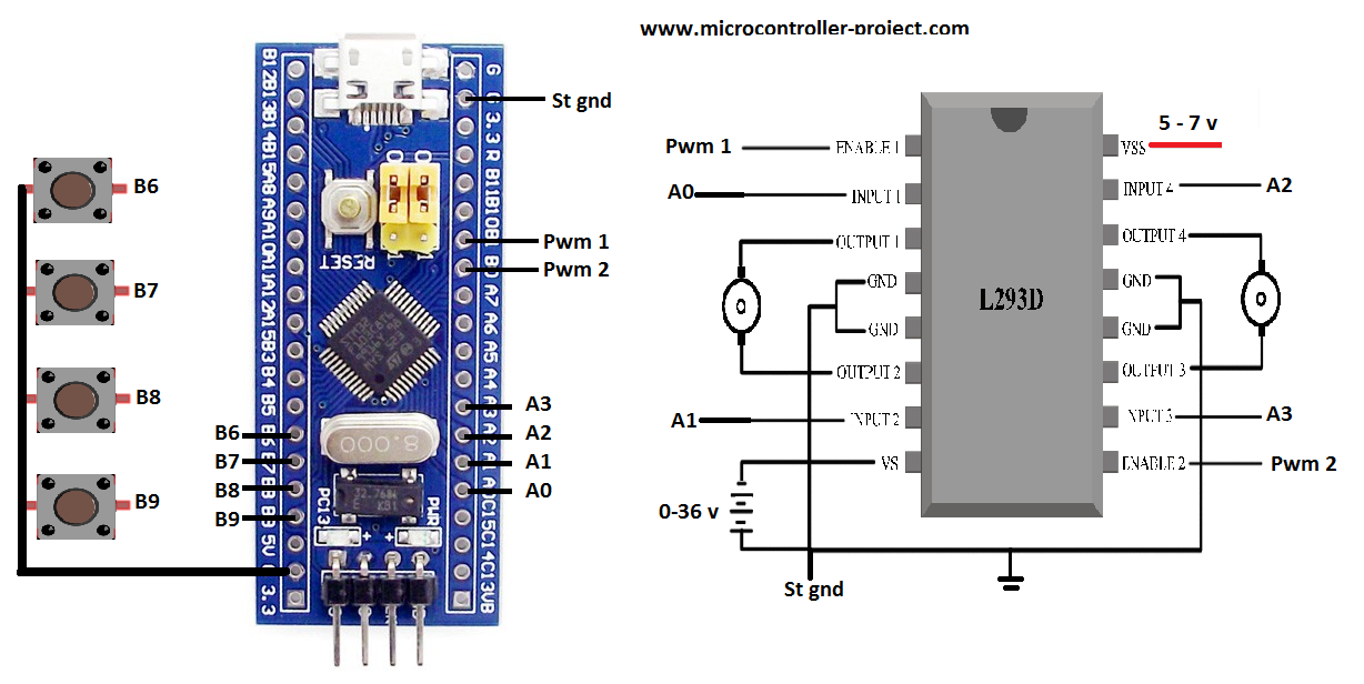
I am going to control the direction of rotation of dc motors and their speed in the project. For this purpose i decided to connect four buttons as input. Buttons will control the direction and speed of the motors. I will discuss purpose of each button later. For four buttons as input i require four gpio’s of stm32 microcontroller declared as input. I declared the Port-B pins 6, 7, 8 and 9 as input. I also activated the pull up resistors associated with these pins.
To control the direction of two dc motors through half h bridge circuits i need four controls. Basically four pgio pins of microcontroller are required to control the direction of two dc motor rotation. I declared four stm32 microcontroller Port-A pins 0, 1, 2 and 3 as output.
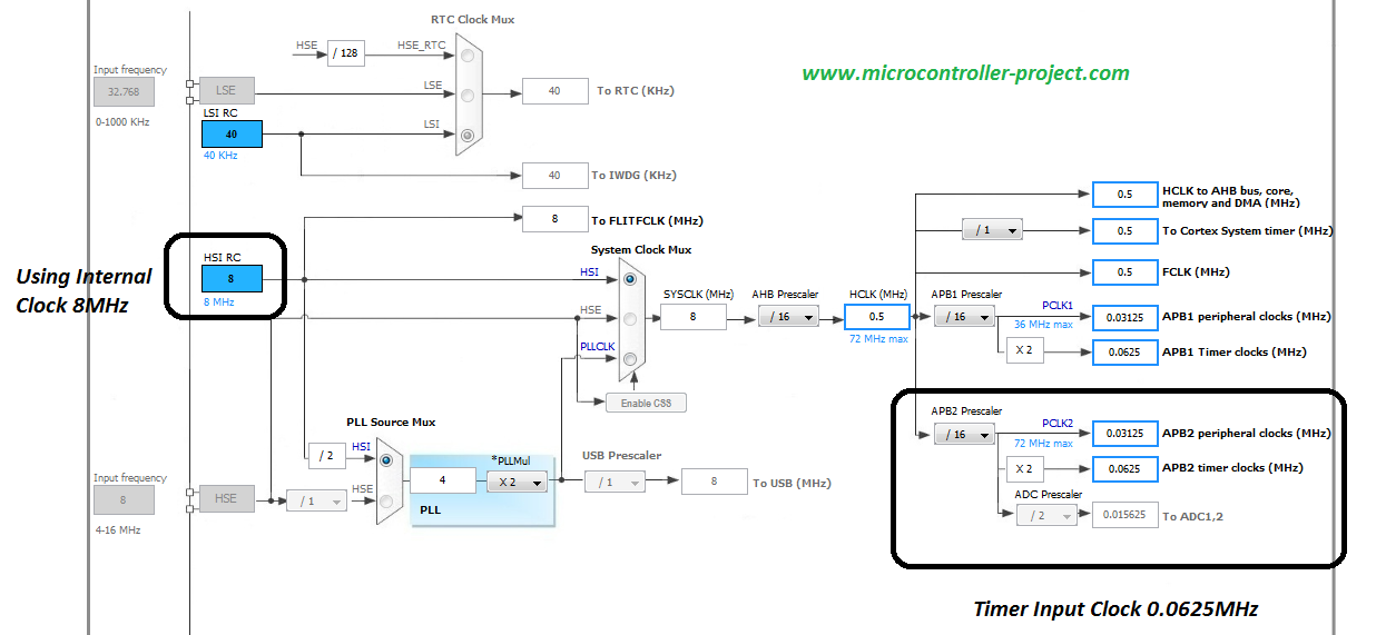
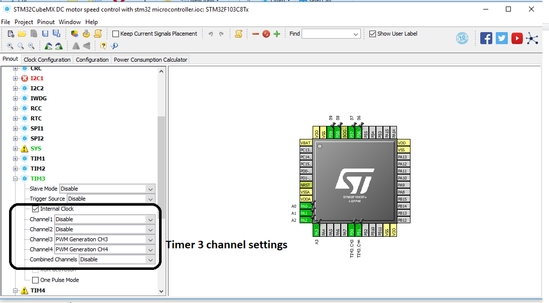
Finally to control the motor speed i need two pwm signals. I am going to use the Port-B pins 0 and 1 as pwm sources. Generating pwm using stm32 is not an easy task. One has to take care of many constraints. I have an another tutorial on how to generate pwm with stm32 microcontroller. I discussed all the constraints frequency, duty cycle and counter etc in that tutorial. Please take that tutorial before moving any further. If you do not take the tutorial you will be unable to understand the code below.
Project circuit
Our 12 volt motors are connected with output pins of l293d. Motor 1 is connected against output pins of channel 1 and motor 2 is connected across output pins of channel 2 of l293d motor driver. Ground pins are grounded.
Note: The ground of stm32 microcontroller power and l293d motor power must be commonly grounded for circuit completion and proper working.
Input buttons functions
- B9 – Pressing button B9 will toggle the rotation direction of dc motor. If its moving in forward direction pressing the B9 button will change the direction to back ward.
- B8 – Pressing button B8 will set the pwm duty cycle to 75% and it lowers with motor rotation speed.
- B7 – Pressing button B7 will set the pwm duty cycle to 50%. Dc motor know rotates at half speed than maximum.
- B6 – Pressing button B6 will set the pwm duty cycle to 25% will further lowers down the rotation speed.
Coming to the code. Main logic of the code is before and between the while 1 loop. If you have gone through the above tutorials on Pwm and stm32cubemx getting started you can easily understand the code statements below. Statements are same as in the previous tutorials only the sequence of statements are changed as desired in the project.
Future work:
With the same code and logic above you can not only drive dc motors but also servo motors. In circuit you have to change some settings like input voltage to l293d for servo motor driving(5 to 12 v). Servo motors work on 50 Hz frequency and duty cycle between 1 milli second to 3 milli second. We generated pwm on 50 Hz frequency. So yon can connect a servo at output and check if the code works(It definitely will). You can also fade an led by connecting it at l293d output with the same code, circuit above. You may need to fix the direction and not change it for led. Since led polarity can’t be changed.
You may also like:


Filed Under: Electronic Projects, Featured Contributions, STM32, STM32.

Hello!
I was using this project with my STM STEVAL-PCC009V2 with STM32F103RBT6 controller ( L298N instead of l293d) and found the tutorial VERY explaining, clear and informative. Explaining Stm32cubemx I found particular clear. Usually I feel using all this stuff Cubemx/Keil confusing but not here. I use Arduino IDE with Generic STM when possible.
And all was functioning without hazzle.
Thanks A LOT!
ER