Engineers Garage

  • Electronic Projects & Tutorials
    • Electronic Projects
      • Arduino Projects
      • AVR
      • Raspberry pi
      • ESP8266
      • BeagleBone
      • 8051 Microcontroller
      • ARM
      • PIC Microcontroller
      • STM32
    • Tutorials
      • Audio Electronics
      • Battery Management
      • Brainwave
      • Electric Vehicles
      • EMI/EMC/RFI
      • Hardware Filters
      • IoT tutorials
      • Power Tutorials
      • Python
      • Sensors
      • USB
      • VHDL
    • Circuit Design
    • Project Videos
    • Components
  • Articles
    • Tech Articles
    • Insight
    • Invention Stories
    • How to
    • What Is
  • News
    • Electronic Product News
    • Business News
    • Company/Start-up News
    • DIY Reviews
    • Guest Post
  • Forums
    • EDABoard.com
    • Electro-Tech-Online
    • EG Forum Archive
  • DigiKey Store
    • Cables, Wires
    • Connectors, Interconnect
    • Discrete
    • Electromechanical
    • Embedded Computers
    • Enclosures, Hardware, Office
    • Integrated Circuits (ICs)
    • Isolators
    • LED/Optoelectronics
    • Passive
    • Power, Circuit Protection
    • Programmers
    • RF, Wireless
    • Semiconductors
    • Sensors, Transducers
    • Test Products
    • Tools
  • Learn
    • eBooks/Tech Tips
    • Design Guides
    • Learning Center
    • Tech Toolboxes
    • Webinars & Digital Events
  • Resources
    • Digital Issues
    • EE Training Days
    • LEAP Awards
    • Podcasts
    • Webinars / Digital Events
    • White Papers
    • Engineering Diversity & Inclusion
    • DesignFast
  • Guest Post Guidelines
  • Advertise
  • Subscribe

Designing an Online UPS – (Part 11/17)

By Dikhsa July 6, 2024

In the previous tutorials, charger for Lead Acid battery and Li-ion battery were designed. This was followed by designing of Square wave inverter and Modified Sine Wave Inverter. Now, it’s time to complete the UPS circuit. The circuit of an inverter includes the following building blocks – 
1) Main Source of Power
2) Battery Charger Circuit
3) Battery 
4) Inverter 
5) Switching Mechanism
The main source of power is usually the AC Mains. The Mains Supply is used to charge a battery through the charger circuit. The battery provides the power backup when the mains supply is cut off. A battery stores electrical energy in the form of DC current. The power backup is provided by connecting the load circuit to the inverter. The inverter draws the power from the charged battery on power failure, converts back the DC power to AC power and provides power backup to the load. This is how any basic UPS works.
Now for completing the UPS circuit, only the designed basic blocks need to be assembled together. But before that it is important to take into account the switching mechanism. In designing any UPS, many factors like cost, size, and a number of output ports, battery backup and output power capacity are important considerations. Apart from these basic factors, one important factor that needs to be considered is the topology or switching mechanism implied in the UPS design. Generally, the topology is one factor that is not usually mentioned on the UPS specifications, but it is equally important like other technical specifications of the UPS.   
There are two basic topologies of the UPS – 
1) Online UPS
2) Offline UPS
Depending upon the application and the load circuit that has to be provided power backup, the UPS topology must be selected. In Online UPS topology, the power is directly supplied to the load via inverter. So, the load circuit is not directly powered by the AC mains but by the inverter. So, when there is a power failure, the Online UPS keeps providing the power to the load without any interruption or fluctuation. So, the load keeps getting the power supply without break. This topology has a drawback that the battery is continuously charged by the AC supply and the charger circuit. If the charger circuit does not have any intelligent circuitry to stop charging the battery once it is fully charged, then the battery may keep on overcharging. So, in online UPS, generally smart battery chargers are incorporated which cut off the battery charging once the battery is fully charged. 
In offline UPS, the load circuit is initially directly powered by the AC mains. On the failure of power supply, the power failure is detected by a control circuit and the power is provided to the load through the battery and inverter after the power failure has already occurred. So, in the offline UPS, the load experiences the power cutoff once before it receives the power backup from the UPS. 
The Online UPS is designed for applications where power should never cut off like for providing power to computer systems in an office or the server rooms. The offline UPS is designed for applications where only proving a power backup is important. Like the offline UPS can be used to provide power backup to industrial machines which does not have time sensitive operation. 
In this tutorial, an online UPS is designed. There are two online UPS circuits designed in this tutorial, of which, in one circuit square wave inverter is used and in other modified sine wave inverter is used. 
Block Diagram – 
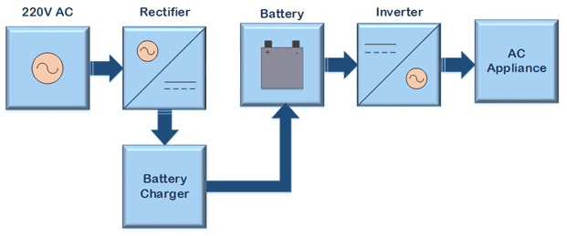
The circuit of the Online UPS can be represented by the following block diagram – 
Block Diagram of Online UPS
Fig. 1: Block Diagram of Online UPS

Note that though there are two circuits designed for online UPS, both circuits have the same block representation. 

Circuit Diagram – 
The Lead Acid battery is used in this Online UPS design. The battery charger has the following circuit diagram – 
Circuit Diagram of LM317 based Lead Acid Battery Charger
Fig. 2: Circuit Diagram of LM317 based Lead Acid Battery Charger

For designing the Online UPS, in one circuit the battery is connected to square wave inverter which has the following circuit diagram – 
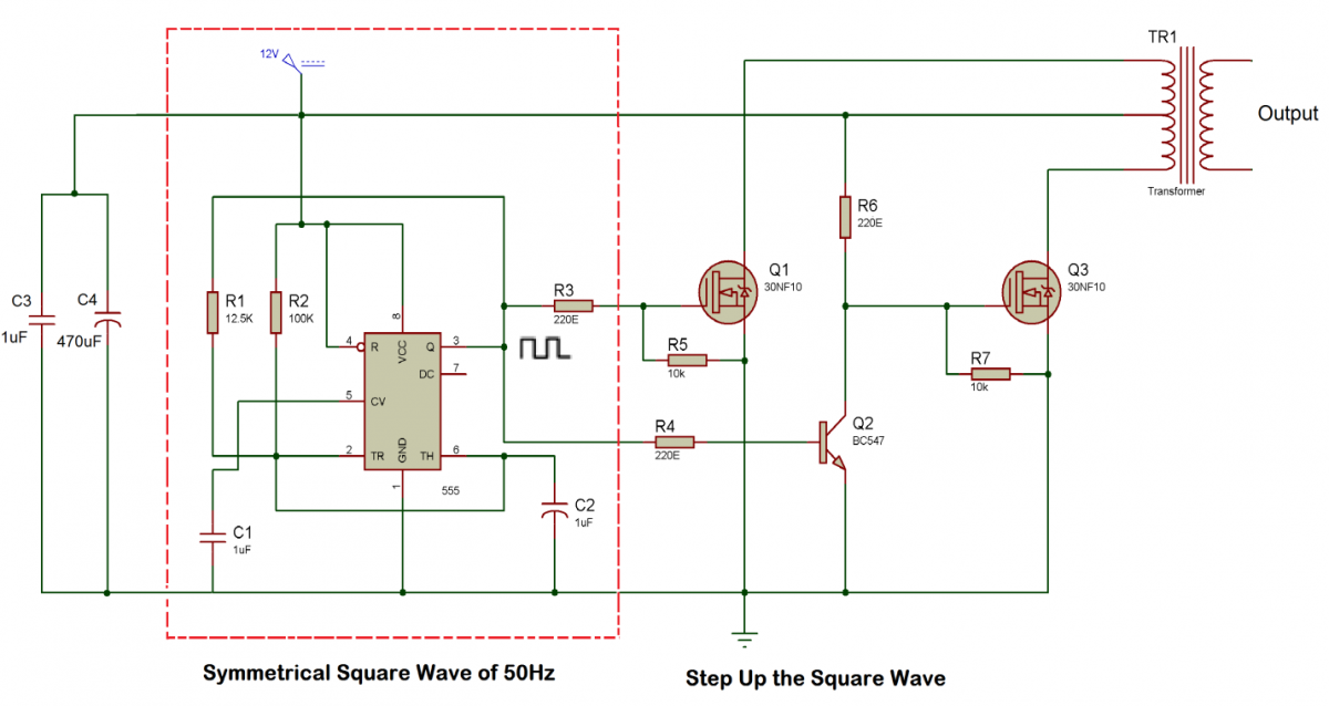
Circuit Diagram of Half Bridge Square Wave Inverter

Fig. 3: Circuit Diagram of Half Bridge Square Wave Inverter

In another circuit, the battery is connected to the modified sine wave inverter which has the following circuit diagram – 

Circuit Diagram of Modified Sine Wave Inverter

Fig. 4: Circuit Diagram of Modified Sine Wave Inverter

Circuit Connections – 
Since the battery charger circuit and inverter circuits have been already designed, now only these circuits need to be assembled together to make the Online UPS. For learning about the lead acid battery charger circuit, check out the following tutorial – 
Designing 12V Lead-Acid Battery Constant Voltage Limited Current Charger for UPS
For learning about the design of square wave inverter, check out the following tutorial – 
Designing Switching Mechanism with Step Up Transformer for Square Wave Inverter
For learning about the design of Modified Sine wave inverter, check out the following tutorial – 
Completing Modified Sine Wave Inverter Design with Full Bridge Circuit and Step Up Transformer
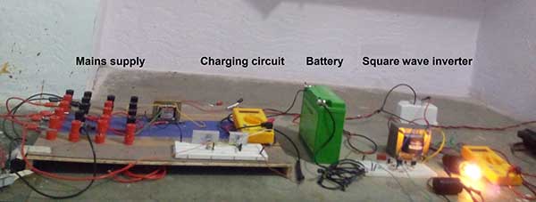
In the Square wave inverter based online UPS, simply the battery terminals of the battery connected to the lead acid battery charger circuit are also connected to the square wave inverter inputs. The load is connected at the output of the square wave inverter. This completes the Online UPS using Square Wave Inverter. 
Prototype of Online UPS Circuit using Square Wave Inverter and Lead Acid Battery Charger
Fig. 5: Prototype of Online UPS Circuit using Square Wave Inverter and Lead Acid Battery Charger

In the Modified Sine wave inverter based online UPS, simply the battery terminals of the battery connected to the lead acid battery charger circuit are also connected to the input of modified sine wave inverter. The load is connected at the output of the modified sine wave inverter. This completes the Online UPS using Modified Sine Wave Inverter. 
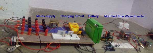
Prototype of Online UPS Circuit using Modified Sine Wave Inverter and Lead Acid Battery Charger

Fig. 6: Prototype of Online UPS Circuit using Modified Sine Wave Inverter and Lead Acid Battery Charger

How the circuit works – 
As the name of this UPS system suggests,  this is the kind of UPS which never switches off and it is always available to supply power to the load appliances when power fails. The online UPS are very efficient in providing a continuous power to the appliance without any delay. In UPS system first, the mains AC is converted to DC for charging the battery. Then the energy stored in the battery is again converted into AC for powering the appliance in case of a power shut down. So this UPS converts power twice before providing power to the load appliance. Due to this fact, the Online UPS is also known as Double-Conversion Online UPS. These UPS systems also ensure that there is a good isolation at the load appliance from the irregularities of the mains supply as the load appliance is not directly connected to the AC Mains. 
As in Online UPS, the battery is always connected to the inverter and inverter is connected with the load appliance. Due to this, the appliance connected to the Online UPS can get a continuous power without experiencing any interruption when the power shut downs. So in these UPS the inverter, as well as the battery, is always in the ON state. This is a downside of the Online UPS. The battery keeps on charging even after getting fully charged. So to make the Online UPS more efficient, one the charger circuit for the battery can have intelligent circuitry to cut off the battery from the charger circuit once it is fully charged. 
Some of the Online UPS designs use a transfer switch for switching the load to the battery when mains AC supply goes out. The transition time of these transfer switches is in few milliseconds which does not affect the working of the appliance when the power goes down. The use of transfer switch in the design of online UPS helps getting the advantages of an offline UPS while the power backup is provided to the load appliance in this kind of UPS without break due to transferring of power source in just few milliseconds. 
In the Online UPS assembled above, any transfer switch for switching the load appliance to the battery is not used. In the circuits, the appliance is always connected to the inverter. The inverter gets the power from the batteries and the rectifier takes care of the charging of the battery. So when mains AC goes out, the charge preserved in the battery supplies power to the load appliance, however, the battery charging stops once it is fully charged.
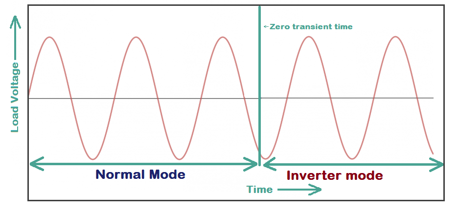
In the online UPS circuits assembled above, there is no interruption or pause in the voltage of the load when the mains power fails. So, there is zero transient time between the power output waveforms observed before and after the power failure.   
Graph showing Zero Transient Time Difference in Online UPS Output Waveform
Fig. 7: Graph showing Zero Transient Time Difference in Online UPS Output Waveform

There are two circuits of the Online UPS designed in this tutorial – 
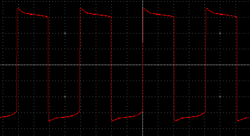
1.Online UPS using Lead acid battery and Square Wave inverter – In this circuit, the load is continuously powered through the square wave inverter. So, the load is in fact powered by a square wave which has zero transient time difference with the input AC Mains. 
2.Online UPS using Lead acid battery and Modified Sine Wave inverter – In this circuit, the load is continuously powered through the modified sine wave inverter. So, the load is in fact powered by a modified sine wave which has zero transient time difference with the input AC Mains. The modified sine wave approximates to an ideal sine wave because of the zero volt level in its waveform. 
Testing the Circuits – 
The Online UPS circuits designed in this tutorial use a 12V lead acid battery. The battery is charged by a charger circuit through the AC mains and the same battery is used by either Square Wave inverter or Modified Sine Wave inverter to draw power for the load. So, there is zero switching time between the power resumption when the power from Mains goes out. An AC bulb is taken as the load for testing the circuits. It was observed that when mains power goes out then the AC bulb connected at the output does not experience any kind of interruption. So the load gets continuous power even when mains power shuts down. The output waveform of the square wave inverter based online UPS is same as that of the waveform which was observed for the square wave inverter.
Graph showing Output waveform of Online UPS Circuit based on Square Wave Inverter
Fig. 8: Graph showing Output waveform of Online UPS Circuit based on Square Wave Inverter

   The efficiency of this UPS is 52 percent as calculated for the inverter. 
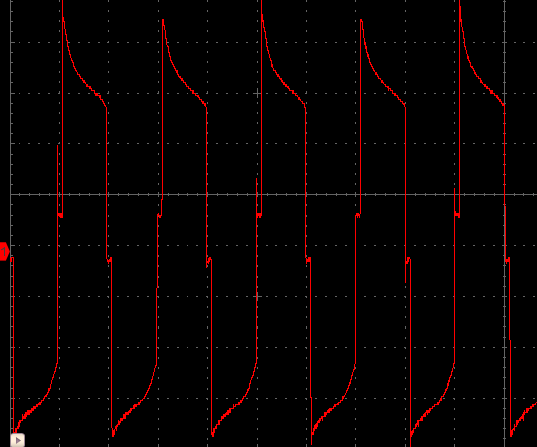
The output waveform of the modified sine wave inverter based online UPS is same as that of the waveform which was observed for the modified sine wave inverter.
Graph showing Output waveform of Online UPS Circuit based on Modified Sine Wave Inverter
Fig. 9: Graph showing Output waveform of Online UPS Circuit based on Modified Sine Wave Inverter

The efficiency of this UPS is 40 percent as calculated for the inverter. The online UPS has several advantages like it is a reliable power back up since the load gets continuous power without delay on power failure. There is zero transient time as no transfer switch is used in the design and there is no switching mechanism. These UPS have less noise and low distortion at the output. There is no brownout (drop in voltage in the mains supply) and so, there is no dropout problem. These UPS have better voltage regulation and as they generate a clean AC so they provide higher degree of protection to the load regardless of any fluctuation in the mains line. There is higher degree of isolation between the Mains AC and the load circuit. The appliance at the output is isolated from any fluctuation in the mains AC supply, this saves the load appliance from any damage. The output frequency remains constant as the inverter is used to supply power to the appliance all the time.  So a constant duty cycle is generated at the output. These UPS provide a liberty to the input and output amplitude and frequency. So a high voltage signal can also be obtained.

Though there are also some disadvantages of these UPS. These require a number of components with high operating temperature. Due to continuous use of inverter, it should be rated for continuous operation. These UPS consumes more power due to double conversion. A higher watt value rectifier is required since it has to supply power to the inverter as well as charge the battery. As all the elements in the Online UPS are always in the ON state which heats up the elements, it decreases the overall reliability of the circuit. The efficiency of the online UPS can be high but due to repetitive double conversion, the efficiency decreases. The efficiency of the square wave inverter based UPS was observed to be 52 percent while that of the modified sine wave inverter based UPS was observed to be only 40 percent. The cooling is necessary due to excessive heat generation in the circuit. Due to the use of high watt rectifier, good rating inverter and due to the addition of cooling process, these inverters are a bit costly to design.
As the output wave has low distortion noise so these UPS can be used to power audio systems or any sensitive electronic devices (depending on the Inverter). Due to zero transfer time, the Online UPS system can be used to provide power backup to sensitive electronic devices like computers and servers. These UPS are incredibly helpful in medical emergencies as they can operate the life support system, health care units, emergency wards and medical equipments. These UPS can also be used to power induction motor and other motor applications. These can be used in telecommunication and IT sector where a small interruption in PCs can affect the work process. These UPS can also be used in military equipments and meteorological devices. So, the online UPS are quite useful where continuous power must be provided through the back up. 
In the next tutorial, the offline UPS will be designed.

You may also like:


  • Introduction to Uninterruptible Power Supply (UPS) and its design (Part…

  • What is Wireless Electric Vehicle Charging System (WEVCS)?

  • What to expect at Embedded World 2023

  • What are the top open-source software systems for home automation?

  • What is the 1-Wire protocol?

  • What is an Integrated Circuit? Specifications to tapeout

Project Video


Filed Under: Power, Tutorials


Next Article

← Previous Article
Next Article →

Questions related to this article?
👉Ask and discuss on Electro-Tech-Online.com and EDAboard.com forums.


Tell Us What You Think!! Cancel reply

You must be logged in to post a comment.

EE TECH TOOLBOX

“ee
Tech Toolbox: 5G Technology
This Tech Toolbox covers the basics of 5G technology plus a story about how engineers designed and built a prototype DSL router mostly from old cellphone parts. Download this first 5G/wired/wireless communications Tech Toolbox to learn more!

EE Learning Center

EE Learning Center
“engineers
EXPAND YOUR KNOWLEDGE AND STAY CONNECTED
Get the latest info on technologies, tools and strategies for EE professionals.

HAVE A QUESTION?

Have a technical question about an article or other engineering questions? Check out our engineering forums EDABoard.com and Electro-Tech-Online.com where you can get those questions asked and answered by your peers!


RSS EDABOARD.com Discussions

  • Right Half Plane Zero
  • dc-dc converter in series
  • Single ended measuring ports and balanced antenna
  • Thermal modelling of repetitive power pulse
  • Permittivity and Permealibility in CST

RSS Electro-Tech-Online.com Discussions

  • Fun with AI and swordfish basic
  • Microinverters and storeage batteries?
  • FFC connector white
  • Is AI making embedded software developers more productive?
  • Can I make two inputs from one??

Featured – LoRa/LoRaWan Series

  • What is the LoRaWAN network and how does it work?
  • Understanding LoRa architecture: nodes, gateways, and servers
  • Revolutionizing RF: LoRa applications and advantages
  • How to build a LoRa gateway using Raspberry Pi
  • How LoRa enables long-range communication
  • How communication works between two LoRa end-node devices

Recent Articles

  • RPi Python Programming 21: The SIM900A AT commands
  • RPi Python Programming 22: Calls & SMS using a SIM900A GSM-GPRS modem
  • RPi Python Programming 23: Interfacing a NEO-6MV2 GPS module with Raspberry Pi
  • RPi Python Programming 24: I2C explained
  • RPi Python Programming 25 – Synchronous serial communication in Raspberry Pi using I2C protocol

EE ENGINEERING TRAINING DAYS

engineering

Submit a Guest Post

submit a guest post
Engineers Garage
  • Analog IC TIps
  • Connector Tips
  • Battery Power Tips
  • DesignFast
  • EDABoard Forums
  • EE World Online
  • Electro-Tech-Online Forums
  • EV Engineering
  • Microcontroller Tips
  • Power Electronic Tips
  • Sensor Tips
  • Test and Measurement Tips
  • 5G Technology World
  • Subscribe to our newsletter
  • About Us
  • Contact Us
  • Advertise

Copyright © 2025 WTWH Media LLC. All Rights Reserved. The material on this site may not be reproduced, distributed, transmitted, cached or otherwise used, except with the prior written permission of WTWH Media
Privacy Policy

Search Engineers Garage

  • Electronic Projects & Tutorials
    • Electronic Projects
      • Arduino Projects
      • AVR
      • Raspberry pi
      • ESP8266
      • BeagleBone
      • 8051 Microcontroller
      • ARM
      • PIC Microcontroller
      • STM32
    • Tutorials
      • Audio Electronics
      • Battery Management
      • Brainwave
      • Electric Vehicles
      • EMI/EMC/RFI
      • Hardware Filters
      • IoT tutorials
      • Power Tutorials
      • Python
      • Sensors
      • USB
      • VHDL
    • Circuit Design
    • Project Videos
    • Components
  • Articles
    • Tech Articles
    • Insight
    • Invention Stories
    • How to
    • What Is
  • News
    • Electronic Product News
    • Business News
    • Company/Start-up News
    • DIY Reviews
    • Guest Post
  • Forums
    • EDABoard.com
    • Electro-Tech-Online
    • EG Forum Archive
  • DigiKey Store
    • Cables, Wires
    • Connectors, Interconnect
    • Discrete
    • Electromechanical
    • Embedded Computers
    • Enclosures, Hardware, Office
    • Integrated Circuits (ICs)
    • Isolators
    • LED/Optoelectronics
    • Passive
    • Power, Circuit Protection
    • Programmers
    • RF, Wireless
    • Semiconductors
    • Sensors, Transducers
    • Test Products
    • Tools
  • Learn
    • eBooks/Tech Tips
    • Design Guides
    • Learning Center
    • Tech Toolboxes
    • Webinars & Digital Events
  • Resources
    • Digital Issues
    • EE Training Days
    • LEAP Awards
    • Podcasts
    • Webinars / Digital Events
    • White Papers
    • Engineering Diversity & Inclusion
    • DesignFast
  • Guest Post Guidelines
  • Advertise
  • Subscribe