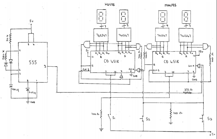
Digital clocks normally function by microcontrollers. Here is a circuit for electronic enthusiasts who can make a digital clock without using any expensive controllers, or having no knowledge of microcontrollers or programming. The whole functioning is solely based on simple IC’s.
Components used
IC 555 (Timer) — one.
CD4518 (CMOS dual up counter) — two.
74LS47 (7-segment display driver) — four.
7-segment displays — four.
Basic Gates (AND, OR).
Working
The clock for the circuit is provided by 555 timer in astable mode (with on-time 2 secs and off-time 58 secs).With every positive edge of timer’s output, one of the counters of CMOS dual up-counter CD4518 (right one in fig.) is clocked, and a BCD output is obtained on the pins 3 to 6. These are given to 7-segment display driver 74LS47 that drives the minute’s display. When the count reaches 9, the other counter of the same IC is clocked, and the current counter is reset. When 59th minute is reached for any hour, the next increment in counter will reset the whole IC, and clock the hour counter (CD4518). When 23 hours is reached, any increment in the hour counter will reset it. The whole set-up can be turned on by pressing S1. The user can adjust the time by pressing on the switches S2 (hours) and S3 (minutes). The on-time of 555-timer is made 2 seconds so that the user doesn’t have any problem in adjusting the time.
Calculations
Calculations
On-time of 555 = 20K ohm * 100 uF = 2secs.
Off-time of 555 timer = 580K ohm * 100uF =58secs.
0.01uF at pin 5 (control pin) of 555 timer is to eliminate the electromagnetic noise. The 100 ohm resistor common to switches S2 and S3 are used as pull-down resistors. 333 ohm resistors and other 100ohm resistors are used to limit the current.
Diodes are small-signal diodes IN4148.
Project Source Code
Circuit Diagrams
Filed Under: 555 Timers, Electronic Projects


Questions related to this article?
👉Ask and discuss on EDAboard.com and Electro-Tech-Online.com forums.
Tell Us What You Think!!
You must be logged in to post a comment.