This project is a light gradient sensitive robot with solar charging capabilities, in other words it seeks out the light to charge itself. It accomplishes this behavior with a set of four light sensitive photoresistors in voltage divider circuits, the Arduino unit reads the four values which correspond to the intensity of the light received by the sensors through its analog read pins. It then applies a high voltage across a reed switch which completes a circuit between a 9v battery, and two toy motors, resulting in turning or moving towards the light.

Fig. 1: Prototype of Arduino based Solar Powered Light Controlled Robotic Tank
These motors were not able to be activated directly with the Arduino, if you get small enough motors, the switching portion of this project may be omitted without loss of functionality.If any of the four photodiodes is registering much higher than the others, it detects which photodiode is receiving the heightened signal and turns or moves in that direction for as long as the heightened signal is being received. This light tracking algorithm can be used to program solar panels to track on the sun, or for control of robot via flashlight, as is demonstrated here. For this project reader needs knowledge of getting start with arduino.
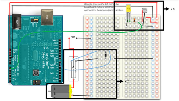
Pictures and diagrams of the full circuit board would be a bit messy in this case, thus I have boxed the main components which are repeated 4 and 2 times respectively in the actual project. The first circuit subsystem is the voltage divider based on a photoresistor which is repeated four times, with each photoresistor being placed on a different side of your robot. Aphotoresistor varies resistance based on light signal received via the photoconductivity of the receiving semiconductor material. The variable resistance produces a variable current in the circuit according to Ohm’s law, V=iR where the voltage V is constant (5V). Be careful not to make the wires leading to any one photodiode excessively long, as you can lose signal due to the internal resistance of the wire and soldering connections. Voltage is supplied to this portion of the circuit directly from the Arduino UNO’s 5V / Gnd pins. The 5V line passes through a 10k Ohms resistor, through the photodiode, and back to ground. An analog in signal is read from between the resistor and the photodiode via Arduino analog in pins. An optional addition is the indicator LED shown going from the other side of the resistor (positive) to ground (negative), this LED will change intensity based on the signal received by the photodiode. If these LED’s are too close to one of the photodiodes, your machine can enter a kind of analog feedback loop in that direction, where it spins in the direction of its own LEDs. I believe I have coded against this possibility, but if you are seeing that behavior, try taking the LEDs out as they are useful only while debugging this portion of the circuit. Four analog in pins should be connected to four iterations of this circuit block. In principle you can increase the number of iterations for increased directional sensitivity, but this is not necessary for this application. The sketch that goes with this project is sensitive to a difference in received light intensity, if all the signals received are very similar, the robot will continue to sample its environment, but remain stationary. As soon as any of the signals is greater than the others by a threshold value, the program enters its motion loop. It determines which photoresistor is receiving the maximum signal and then applies current to the motor which moves the robot in the correct corresponding direction. This action continues as long as that photoresistor is receiving maximum intensity, and there is a great enough difference between the read values.

Fig. 2: Image showing circuit connections of Photo resistor on Robotic Tank for detection of Flashlight
The second blocked portion of the circuit is only necessary if you need more power to the motors then the Arduino can supply directly from its PWM output pins. My chassis / tracks / motor is from a Chinese toy, the Arduino was having trouble driving the motors with the tracks on, so I built in a switching block to the circuit that allows the PWM output to flip a reed relay that completes a circuit to a 9V battery. The reed relay works via an electromagnet which when activated by the lower current (Arduino) causes the contact points within the switch to become magnetized and close the circuit. In principle you can drive very large electric motors with this concept by selecting the correct reed relay. I did not need much more power, so a 9V battery was plenty, the switch I used is in the parts lest section. Since this component is operated via electromagnetic field, a transient protection diode is necessary, since the collapsing magnetic field (when the switch is turned off) can cause a current spike to travel back towards the Arduino as predicted by Maxwell’s equations. A good discussion on how to implement this particular reed relay switch without causing damage to your board can be found here.

Fig. 3: Image showing circuit connections of Battery wires on Robotic Tank
This portion of the circuit is repeated twice corresponding to two motors, and as stated, if you are able to power your motors directly with Arduino, you may omit this portion of the project without loss of functionality.
Circuit Diagrams & Components Used
Circuit Diagram
Voltage Divider

Fig. 4: Circuit Diagram of Voltage Divider Network used for detection of Flashlight
Switching Circuit

Fig. 5: Circuit Diagram of DC Motor Controller used for light guided navigation of Robotic Car
Please refer Circuit Diagram Tab for Complete Circuit used in the Project
Components Used
4x Resistor, 10 K Ohms
4x Photo Light Sensitive Resistor Photo Resistor, Opto Resistor 5mm GL5516 5516
4x LED
RadioShack® 1.5W Solar Panel 9V
Toy tracks / platform / motors (2)
2x Reed Switches (OMR-C-105H)
You may also like:


Project Source Code
###
constintfrontPin = A0; constintleftPin = A1; constintrightPin = A2; constintbackPin = A3; constintleftMotor = 9; constintrightMotor = 10; intthreshHold = 170; int Direction; int direction1; int direction2; int Delay = 25; int Delay2 = 25; void setup() { pinMode(frontPin, INPUT); pinMode(leftPin, INPUT); pinMode(rightPin, INPUT); pinMode(backPin, INPUT); pinMode(leftMotor, OUTPUT); pinMode(rightMotor, OUTPUT); digitalWrite(leftMotor, HIGH); digitalWrite(rightMotor,HIGH); delay(100); digitalWrite(leftMotor, LOW); digitalWrite(rightMotor, LOW); delay(100); digitalWrite(leftMotor, HIGH); digitalWrite(rightMotor, HIGH); delay(100); digitalWrite(leftMotor, LOW); digitalWrite(rightMotor, LOW); delay(1500); Serial.begin(9600); } void loop() { int Direction; int direction1; int direction2; intfrontSignal = 1023 - analogRead(frontPin); intleftSignal = 1023 - analogRead(leftPin); intrightSignal = 1023 - analogRead(rightPin); intbackSignal = 1023 - analogRead(backPin); Serial.println(frontSignal); Serial.println(leftSignal); Serial.println(rightSignal); Serial.println(backSignal); // frontSignal + leftSignal + rightSignal + backSignal<= threshHold if (abs(frontSignal-leftSignal)+abs(frontSignal-rightSignal)+abs(frontSignal-backSignal) >= threshHold ) { Serial.println("motion loop"); direction1 = max(frontSignal, leftSignal); direction2 = max(rightSignal, backSignal); Direction = max(direction1, direction2); //Loop here is entered only if the light received is not evenly distributed. if (frontSignal == Direction) { do { digitalWrite(leftMotor, HIGH); digitalWrite(rightMotor, HIGH); delay(Delay2); digitalWrite(leftMotor, LOW); digitalWrite(rightMotor, LOW); delay(Delay); frontSignal = 1023 - analogRead(frontPin); leftSignal = 1023 - analogRead(leftPin); rightSignal = 1023 - analogRead(rightPin); backSignal = 1023 - analogRead(backPin); direction1 = max(frontSignal, leftSignal); direction2 = max(rightSignal, backSignal); Direction = max(direction1, direction2); Serial.println("Forward"); } while(frontSignal == Direction && abs(frontSignal-leftSignal)+abs(frontSignal-rightSignal)+abs(frontSignal-backSignal) >= threshHold); digitalWrite(leftMotor, LOW); digitalWrite(rightMotor, LOW); } else if (leftSignal == Direction) //Signal is greatest on the left { do { Serial.println("Left"); digitalWrite(rightMotor, HIGH); delay(Delay2); digitalWrite(rightMotor, LOW); delay(Delay); frontSignal = 1023 - analogRead(frontPin); leftSignal = 1023 - analogRead(leftPin); rightSignal = 1023 - analogRead(rightPin); backSignal = 1023 - analogRead(backPin); direction1 = max(frontSignal, leftSignal); direction2 = max(rightSignal, backSignal); Direction = max(direction1, direction2); } while(leftSignal == Direction && abs(frontSignal-leftSignal)+abs(frontSignal-rightSignal)+abs(frontSignal-backSignal) >= threshHold); digitalWrite(rightMotor, LOW); } else if (rightSignal == Direction) //Signal is greatest on the right. { do { Serial.println("Right"); digitalWrite(leftMotor, HIGH); delay(Delay2); digitalWrite(leftMotor, LOW); delay(Delay); frontSignal = 1023 - analogRead(frontPin); leftSignal = 1023 - analogRead(leftPin); rightSignal = 1023 - analogRead(rightPin); backSignal = 1023 - analogRead(backPin); direction1 = max(frontSignal, leftSignal); direction2 = max(rightSignal, backSignal); Direction = max(direction1, direction2); } while(rightSignal == Direction && abs(frontSignal-leftSignal)+abs(frontSignal-rightSignal)+abs(frontSignal-backSignal) >= threshHold); digitalWrite(leftMotor, LOW); } else if (backSignal == Direction) //Signal is greatest behind. { do { Serial.println("Back"); digitalWrite(leftMotor, HIGH); delay(Delay2); digitalWrite(leftMotor, LOW); delay(Delay); frontSignal = 1023 - analogRead(frontPin); leftSignal = 1023 - analogRead(leftPin); rightSignal = 1023 - analogRead(rightPin); backSignal = 1023 - analogRead(backPin); direction1 = max(frontSignal, leftSignal); direction2 = max(rightSignal, backSignal); Direction = max(direction1, direction2); } while(backSignal == Direction && abs(frontSignal-leftSignal)+abs(frontSignal-rightSignal)+abs(frontSignal-backSignal) >= threshHold); digitalWrite(leftMotor, LOW); } } else if(abs(frontSignal-leftSignal)+abs(frontSignal-rightSignal)+abs(frontSignal-backSignal) <= threshHold) { int difference = abs(frontSignal-leftSignal)+abs(frontSignal-rightSignal)+abs(frontSignal-backSignal); Serial.println("Signal differential is equal to "); Serial.println(difference); digitalWrite(leftMotor, LOW); digitalWrite(rightMotor, LOW); delay(1000); // Else sample environment at a rate of 10 hz } else { digitalWrite(leftMotor, LOW); digitalWrite(rightMotor, LOW); } }###
Circuit Diagrams
Project Video
Filed Under: Electronic Projects
Filed Under: Electronic Projects

Questions related to this article?
👉Ask and discuss on Electro-Tech-Online.com and EDAboard.com forums.
Tell Us What You Think!!
You must be logged in to post a comment.