A kind of Read Only Memory (ROM), which can be written and erased by means of electrically programming the data, is called Electrically Erasable Programmable Read Only Memory (EEPROM). Once programmed the data it will remain in the memory for a very long time even if there is no power available. The EEPROM comes in small sized chips which can be interfaced with microcontrollers in a system. Most of the microcontrollers have built-in EEPROM with reasonable memory size so that for small kind of applications an extra memory chip can be avoided.
A microcontroller uses the EEPROM memory to store its data like sensor value, or a particular count or image data for a long period of time uses the EEPROM memory. The EEPROM memory is also used to save the data before the system switches itself off so that the same data can be retained next time when the system is turned on.The Arduino board has an AVR microcontroller in it which also has a built-in EEPROM memory. The memory size varies with the Arduino boards and the microcontroller used in them. The Arduino can be interfaced with the other devices with the help of its digital pins, analog pins and with the help of serial communication protocol.
The serial port of the microcontroller provides the easiest way by which the user and the microcontroller can write their data in the same medium and both can read each other’s data. When the serial port of the microcontroller is connected to the PC and the incoming and outgoing data is monitored using software and displayed in a window, it forms the simplest text user interface (TUI) setup for the microcontroller.This particular project demonstrates how to write some text starting from a particular memory location of the internal EEPROM of the Arduino and later read the entire EEPROM memory and display it on any serial monitoring software or using the Arduino’s serial monitor itself to find the same data once written.
The Arduino is an easy prototyping platform in which the hardware is very simple to use and to be connected with any other system. The programing environment is also very easy to start with and has lot of built-in functions for every simple and complex task. The AVR microcontroller boards which are provided with all the basic circuitry for the operation of the microcontroller which has been flashed with the arduino boot-loader are called arduino boards. The arduino can communicate with the other devices using its digital I/O, serial port, I2C port, SPI port etc. In this particular project the Arduino pro-mini board is used which is then programmed with the help of Arduino IDE version 1.0.3 on windows operating system. The Arduino pro-mini board has ATMEGA328 microcontroller inside it which has a 1Kb of internal EEPROM memory. The internal EEPROM memory can be easily accessed using the built-in functions provided by the Arduino IDE. The board has also one set of Tx and Rx pins with the help of which the board can be interfaced with the serial port. The image of the Arduino pro-mini board and the Arduino IDE is shown in the following;
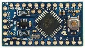
Fig. 2: Typical Arduino Pro-Mini Board
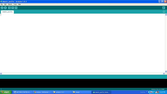
Fig. 3: Arduino IDE Software Window
Since the arduino pro-mini board has no circuitary for interfacing it with the serial port or the USB port of the PC, an external USB to TTL converter board is required to connect it with the PC. This hardware helps in programming the arduino board and also helps in the serial communication with the PC through the USB port of the PC.
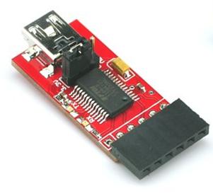
Fig. 4: External USB to TTL converter board for programming Arduino and serial communication
It is assumed that the reader has gone through the project how to get started with the arduino and done all the things discussed in it. There are some built-in functions in the arduino IDE which helps in the serial communication process.There is a function which helps to initialize the serial communication port with a particular baud rate and there are functions to send data to the serial port. The functions used in this projects are namely Serial.begin(), Serial.print() and Serial.write(). The details of these functions and similar functions for the serial communication are already discussed in previous projects on how to do serial communication with the Arduino, how to send and receive serial data using arduino, how to do serial debugging with the Arduino.
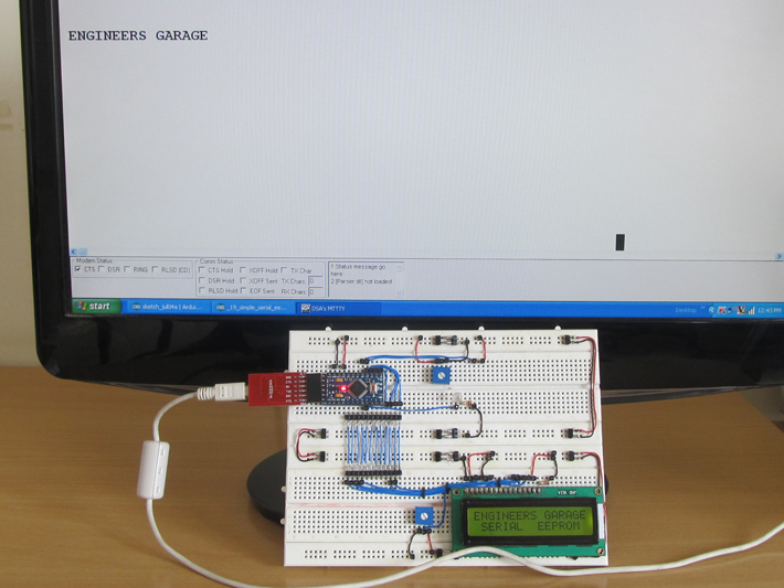
Project Source Code
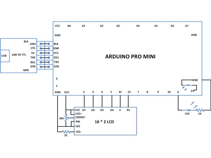
### /*================================= EG LABS ======================================= Clear the entire EEPROM, write it with some data and read it back The circuit: * LED attached from pin 6 to ground through a 1K resistor LCD: * LCD RS pin to digital pin 12 * LCD Enable pin to digital pin 11 * LCD D4 pin to digital pin 5 * LCD D5 pin to digital pin 4 * LCD D6 pin to digital pin 3 * LCD D7 pin to digital pin 2 * LCD R/W pin to ground * 10K resistor: * ends to +5V and ground * wiper to LCD pin 3 * LED anode attached to digital output 6 * LED cathode attached to ground through a 1K resistor //================================= EG LABS =======================================*/ #include <EEPROM.h> #include <LiquidCrystal.h> LiquidCrystal lcd(12, 11, 5, 4, 3, 2); // initialize the LCD library with the numbers of the interface pins int address = 0; // the variable which holds the address in the eeprom int read_value = 0; // the variable which holds the data which is read from the eeprom char serial_in_data; // the variable which holds serial input data int led = 6; // variable which holds the pin number at which the LED is connected char eeprom_data [] = " ENGINEERS GARAGE "; // data to be written on EEPROM int i; void setup() { pinMode(led, OUTPUT); // initialize the led pin as an output. lcd.begin(16, 2); // set up the LCD's number of columns and rows: lcd.print("ENGINEERS GARAGE"); lcd.setCursor(0, 1); lcd.print(" SERIAL EEPROM "); Serial.begin(9600); // initialize the serial port with baud rate 9600 for(address = 0; address < 1024; address ++) // fill the entire eeprom memory with white spaces EEPROM.write(address, ' '); address = 0; for(i = 0; eeprom_data [i] != '�'; i ++) { EEPROM.write(address, eeprom_data [i]); address ++; } for(address = 0; address < 1024; address ++) // read the entire EEPROM memory { read_value = EEPROM.read(address); Serial.write(read_value); } } void loop() { //---- blink LED -----// digitalWrite(led, HIGH); delay(1000); digitalWrite(led, LOW); delay(1000); //---- blink LED -----// } ###
Circuit Diagrams
Project Components
Project Video
Filed Under: Arduino
Filed Under: Arduino


Questions related to this article?
👉Ask and discuss on EDAboard.com and Electro-Tech-Online.com forums.
Tell Us What You Think!!
You must be logged in to post a comment.