A major challenge in electronic circuit design is selecting suitable components that perform well under all operating conditions. This is particularly essential in regards to the safe operating limits of current, voltage, power, and temperature.
Here, we’ll focus on temperature. Every electronic component generates heat while transferring power. Bear in mind there are no perfect components in electronics because each one sustains certain power losses. So, it’s impossible to obtain full power output because some is lost due to heat energy, which requires thermal management.

There are various techniques for maintaining the temperature of electronic components such as a heat sink, a thermoelectric cooler (TEC), forced air pressure, a fan, etc.
In this article, we’ll discuss how to best select a heat sink and cooling fan . A heat sink comprises a good thermally conductive material to disperse excess heat and improve electronic reliability. A heat sink is typically outfitted with a fan to help maintain the temperature by blowing out the excess heat.
The heat sink
In electronics, every component has an operating temperature range above which the components may overheat or fail. To operate the components in the ideal temperature range, a heat sink or thermal management system is typically used for a longer working life.
Principle
A heat sink works on the principle of Fourier’s law, which states that whenever any two bodies with temperature differences are in contact, the heat will transfer from the high-temperature area to the low-temperature area.
Types of heat sinks
There are two primary types of heat sinks.
1. Active heat sink – uses a cooling fan to cool down the heat sink via a forced air convention process — offering high cooling performance. You can hear these fans in laptops and PCs.
2. Passive heat sinks – use zero fans and are more reliable because there are no moving parts. These heat sinks use natural air convention for heat removal, and heat transfer depends on the air surrounding the heat sink.
Heat sink selection
Most of the heat in these devices is dissipated by switching devices like MOSFETs and ICs. Let’s take an example of the common voltage regulator, ST’s 7805, and select a proper heat sink for this.
Parameters
Every IC manufacturer mentions parameters to follow for ideal heat sink selection for an IC.
These include:
1. Thermal resistance (θ/Rth) – compare the thermal resistance with the basic circuit design resistance. The normal resistance restricts the flow of current through it, whereas thermal resistance opposes the heat flow. So, the lower the thermal resistance, the more heat can be transferred from one component into the surrounding air.
Unit – °C/W; for a one-watt increase in power, the temperature will increase by X°c.
Generally, thermal resistance (θ) is measured relative to the ambient temperature (TA) and denoted by θJA. Its value is typically given in the IC datasheet. The ambient temperature is the surrounding temperature where the component should be placed.
2. Maximum junction temperature (TJ) – the image below shows the junction of the IC, and this junction has an operating temperature limit as mentioned in the manufacturer datasheet.
When any component transfers heat, its junction temperature will increase due to thermal resistance. When the junction temperature reaches its operating limit, the IC begins malfunctioning and may get faulty or fail. To maintain the IC’s junction temperature, a proper heat transfer system is required.
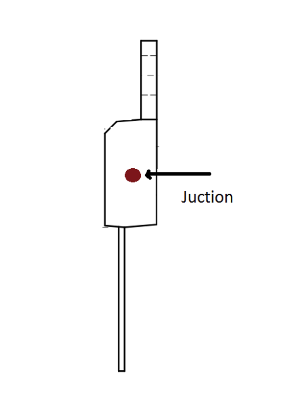
Figure 1. The IC junction
The junction temperature is what “decides” on the maximum allowable limits of power dissipation of any device.
The equation which is typically used for calculating the maximum power dissipation that an IC can dissipate under its operating junction temperature is:
θJA = TJ(max) – TA/ Pd(max)…………Eq.1
Pd(max) = maximum power dissipation that a device can dissipate under the junction’s temperature range.
Now, let’s take the values from the datasheet of 7805 for the TO-220 package, using the above equation…
θJA = 50°C/W
TJ(max) = 125°
TA = 35 °
Upon calculation, we get:
Pd(max) = 1.8W
Natural convection design
Let’s first consider and calculate this heat sink design.
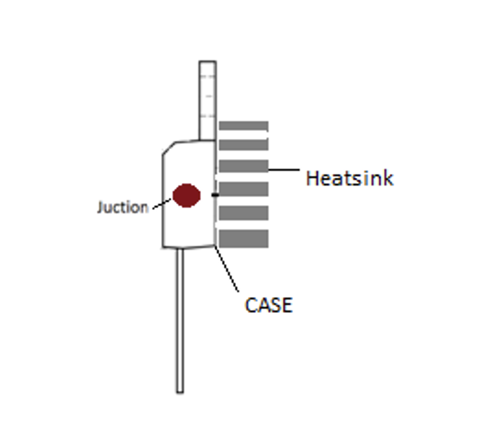
Figure 2. The junction with the heat sink placement.
1. Calculating the thermal resistance of the heat sink
The θJA is made up of two separate resistances:
- Thermal resistance junction to case θJC
- Thermal resistance case to ambient θCA
The θJC cannot be altered as it always depends on the manufacturer and is generally low. The θCA is divided into two resistances as per below:
θCA = θCS + θSA.
θCS = Thermal resistance of interface compound used
θSA = Thermal resistance of the heat sink
So, we get:
θJA = θJC + θCA
θJA = θJC + θCS + θSA.
Based on equation #1, we get:
(TJ(max) – TA/ Pd(max)) = θJC + θCS + θSA
Rearranging for θSA:
θSA = (TJ(max) – TA/ Pd(max)) – θJC – θCS…….Eq.2
Given the parameters in the manufacturer’s datasheet:
TJ, Pd, θJC
TA = is the user-defined parameter as per the environment condition. Typically, it’s from 30°- 40° in forced air convection (fan) and 50-60° in the natural air in enclosed space.
θCS = depends on the interface material and its thickness, flatness, and the mounting pressure and contact area of the IC’s heat sink. This data can be found in the manufacturer’s datasheet.
Based on equation #2, we’ll calculate the thermal resistance of the heat sink, which can maintain the IC’s junction temperature at or below the operating limits.
For the natural convection in open air, let’s consider the following:
TA = 40°C/W
- If the input voltage, Vin = 12V, input current, Iin = 1A
- Then, the output voltage Vo = 5V, output current, Io = 1A
Pd = (Vin*Iin – Vo*Io)
Pd = 7W
The datasheet value for TO-220,7805 is:
TJ(max) = 125°
θJC = 5°C/W
θCS is considered an interface compound, a thermal silicon compound that’s available in the form of a grease paste. For a typical layer thickness of 0.5mm, the thermal resistance is 0.98°C/W
By putting all the values in equation #2, we get:
Natural convection Thermal Resistance(Heatsink), θSA = 6.2°C/W
So, we can use a heat sink with a thermal resistance of equal or below the θSA value.
2. Calculating the volume of the heat sink in a natural convection.
The volume of the heat sink can be calculated use the equation below.
Volume(heatsink) = Volumetric Resistance(Cm3 °C/W) / θSA(°C/W)
The volumetric resistance is based on the air flow and can be calculated by following this table’s guide:

θSA = 6.2°C/W as calculated above
Volume(Heatsink) = 600/6.2
Volume(Heatsink) =97 cm3
The heat sink design for (ST) 7805 IC in natural convection with a maximum power dissipation of 7W is:
Thermal resistance(Heatsink) <=6.2°C/W
Volume(Heatsink) =97 cm3
The heat sink design for forced convection
The thermal resistance parameter can be changed depending on the airflow. The measuring unit for the airflow is LFM (linear feet per minute) or CFM (cubic feet per minute). LFM defines the velocity of the air, while CFM measures the volume.
Generally, the fan comes with a CFM rating as they’re usually rated for the quantity of air they can move.
Forced or natural convection can be implemented for thermal management; it depends on the cost and space for any application. This is where the volume of the heat sink matters.
Volume(heatsink) = Volumetric Resistance(Cm3 °C/W) / θSA(°C/W)
θSA = 6.2°C/W as calculated above
Volumetric resistance from above table for 200(LFM) = 200
Volume(Heatsink) = 200/6.2
Volume(Heatsink) =32 cm3
The heat sink and fan design for the 7805 IC in forced convection with a maximum power dissipation of 7W is:
Thermal resistance(Heatsink) <=6.2°C/W
Volume(Heatsink) =32 cm3
Fan (LFM) = 200
Do we need a heat sink in our design?
There are a few equations by which we can determine if there’s a need for a heat sink in our design or if it’s necessary to replace the IC with higher wattage one.
First, let’s calculate θJA(Total) using the equation #1.
θJA(Total) = TJ(max) – TA/ Pd(max)
Case #1. A heat sink is not required
If, θJA(Total) > θJA
Let’s understand this based on the below example for 7805 IC.
Assume…
TA= 35°
TJ= 125°
θJA = 50°C/W
Pd = 1W
By placing all of the values in equation #1, we get:
θJA(Total) = 90°C/W
Case #2. A heat sink is required
θJC < θJA(Total) < θJA
Let’s understand this based on the below example for 7805 IC.
Assume…
TA= 35°
θJc = 5°C/W
TJ= 125°
θJA = 50°C/W
Pd = 2W
By placing all of the values in equation #1, we get:
θJA(Total) = 45° C/W
Case #3. The need for a higher wattage IC
θJA(Total) < θJC
Let’s understand this based on the below example for 7805 IC.
Assume…
TA= 35°
θJc = 5°C/W
TJ= 125°
Pd = 20W
By placing all of the values in equation #1, we get:
θJA(Total) = 4.5° C/W
Other factors to consider while designing heat sink
1. The width of the heat sink. By increasing the width of the heat sink by a factor of two, three, or four can increase the power dissipation capability by two, three, or four.

Figure 3. The width of the heat sink
2. The length of the heat sink. An increase in the length of the fin length by a factor of two, three, or four increases the power dissipation capability by a factor of 1.4, 1.7, and 2.
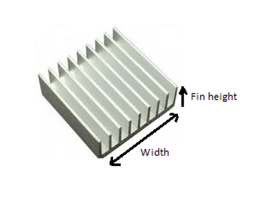
Figure 4. The length of the heat sink
3. The radiation in natural convection. The radiation in natural convection is responsible for up to 25% of the total heat dissipation. It’s recommended to paint the heat sink to enhance its radiation unless the component is not facing any hotter areas around it.
4. Adding fins to the heat sink. Adding the fins to the heat sink increases its surface area, which improves heat dissipation capability and is more economical.
5. The placement of the heat sink. To make natural convection more effective, the direction of fins should be parallel to the gravitation force direction.
There are two methods of mounting a heat sink:
- Horizontal mounting: the bottom side of the heat sink restricts airflow from the bottom to the top, so this placement is not ideal.
- Vertical mounting: the heat sink acts as a vertical channel in which air goes from the bottom and comes out from the top. So, this is a better placement.
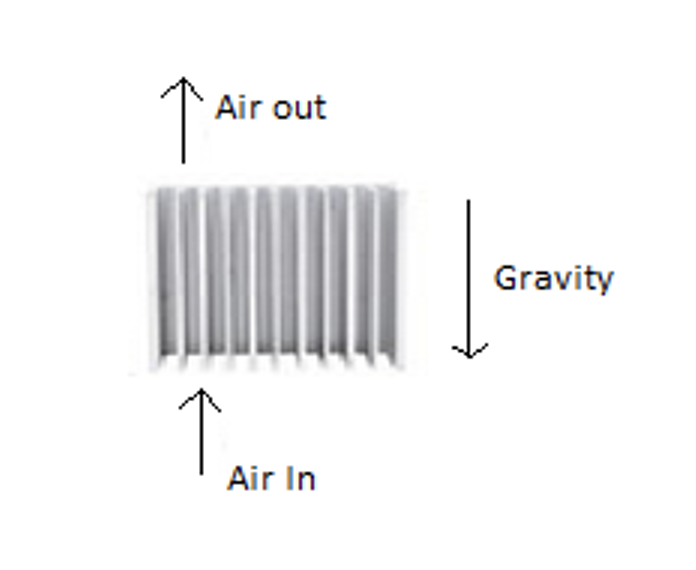
Figure 5. Vertical mounting
Key points
- Forced convection is more effective than natural convection, but it increases the cost of the system.
- Vertical mounting gives better heat transfer results than horizontal one.
- A smaller heat sink with forced convection can do the same job as a large heat sink with natural convection.
- It’s better to increase the width of the heat sink for more efficient heat dissipation.
- A heat sink with fins performs better than a basic one.
- A painted heat sink enhances the radiation phenomena of heat transfer.
You may also like:


Filed Under: Power Management, Tutorials

Questions related to this article?
👉Ask and discuss on EDAboard.com and Electro-Tech-Online.com forums.
Tell Us What You Think!!
You must be logged in to post a comment.