Transformer is an electrical device used to step up and down the AC voltages. There are two types of transformers: Step up and step down transformer. Step up transformer increases the magnitude of voltage while step down transformer decrease the magnitude of voltage. Depending on the ratio of the number of turns in the primary & secondary winding a transformer is characterized as step up or step down. Click to learn more about transformer.

Fig. 1: A Transformer
The metal body is known as transformer’s core. It is specially designed to reduce eddy current and hysteresis losses.

Fig. 2: Outer or Secondary Winding of Transformer
The outer winding shown in the above image is the secondary winding. It is covered with an insulating paper. The output is taken from this winding.
Output Wiring

Fig. 3: Variable Output Transformer
This transformer is a variable output transformer i.e., the output of the transformer is various AC voltages like 3V AC. 6V AC etc. The output voltage is dependent on the number of turns of secondary coils. Hence in order to provide different output voltages the output wires as shown in the figure above are brought out of the secondary coil from different turns respectively.
Insulating Layer & Primary

Fig. 4: Insulating Layer of Transformer
Under the secondary coil wires we can see an insulating material layer which separates the secondary coil with the primary coil.

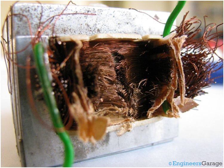
Fig. 5: Primary Winding Under Insulating Layer
On cutting the insulating material we can see the primary winding.

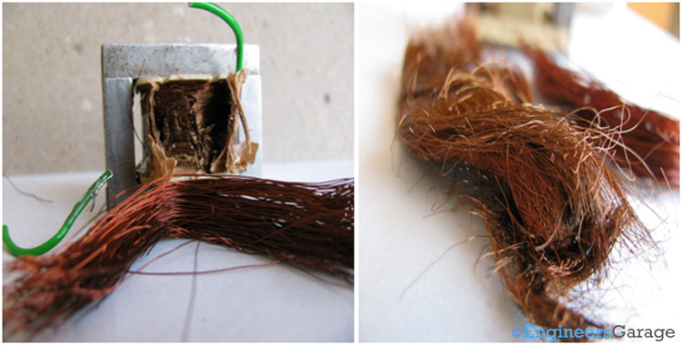
Fig. 6: Closer View of Primary Winding Coils
The wires used in primary coils are comparatively thin and has higher number of turns.
Insulating Material & Core

Fig. 7: Primary and Secondary Coils of Transformers
The above image shows the primary and secondary coils. The first image is of secondary coil and the second image is of primary coil.

Fig. 8: Insulating Material and Transformer Core
In the above image you can see the insulating material which separates the primary & secondary winding. In the image just next to it transformer core is shown.
Working

Fig. 9: Image Showing Thin Metal Plates that make a Transformer’s Core and their Positioning
A lot of thin metal plates are used to make a transformer’s core. It is structured to leave some gaps in order to reduce eddy current and hysteresis losses.

Fig. 10: Metal Plates Shown Individually
These are the plates covered up on the plastic shape shown in below image to structure Transformer’s core.
Part IX

Fig. 11: Plastic Body of Transformer’s Core that has the Metal Plates
Working of a Transformer: We have seen a transformer contains two coils. Primary coil is attached with the input power source while secondary coil provide output voltage. When a varying current enters in the primary coil of the transformer, it generates a magnetic flux in the core and thus a varying magnetic field in the secondary coil. This varying magnetic field across the secondary coil produces a voltage in secondary coil. This effect is called mutual induction.
The voltage in secondary coil depends on the input voltage and number of turns in both coils.
Filed Under: Insight


Questions related to this article?
👉Ask and discuss on EDAboard.com and Electro-Tech-Online.com forums.
Tell Us What You Think!!
You must be logged in to post a comment.