The majority of sensors have an analog output. Few sensors come with a built-in controller and can stream the output measurements over a digital protocol. That is why analog to digital conversion is one of the basic features that every microcontroller/port has. The other basic features include digital input/output, analog output, PWM generation, and serial data communication.
With MicroPython, reading analog voltages from sensors in the supported microcontroller boards/ports is handy. Compared to other popular microcontroller ecosystems like Arduino, MicroPython even lets you access the internals of ADC peripherals of the supported boards. You can not only read analog voltages; you can even configure ADC peripherals to personalized settings. This article will discuss ADC modules in MicroPython and examine how MicroPython firmware is used to read analog signals in ESP8266 and ESP32.
Machine module
MicroPython consists of several hardware-specific modules. One of these modules is the machine. This module consists of several classes that are written for controlling digital input/output, controlling output signals from external devices, pulse width modulation, analog to digital conversion, controlling ADC peripherals, UART, SPI, I2C, I2S, Timer, RTC, Watchdog timer, and manage SD card. There is an ADC class in the machine module for controlling analog-to-digital conversions—an additional class, ADCBlock, written for custom configuration and management of ADC peripherals.
ADC class in machine module
The ADC class is responsible for providing an interface to analog-to-digital converters in MicroPython ports. It provides clean and straightforward functions that allow you to configure ADC settings and retrieve ADC readings as discrete values or direct voltages. This module is imported in a MicroPython script using the following statement.
from machine import ADC
After importing the ADC class from the machine module, one must instantiate an ADC object. This is done by calling the machine.ADC() method with an assignment to a variable. The machine.ADC() method has the following prototype.
class machine.ADC(id, *, sample_ns, atten)
The ADC() method takes three arguments – id, sample_ns, and atten, which sample_ns and atten are optional parameters. The ID is the identification of the ADC source. It can be either an ADC channel or an ADC pin. The identification of the ADC source depends on the specific port. It is specified by an integer representing the ADC channel or by a PIN object. The parameter sample_ns is the sampling time in nanoseconds. The parameter atten specifies the input attenuation.
Once the ADC object is defined with the help of the ADC() constructor, it can be modified later by calling the ADC.init() method. The method has the following prototype.
ADC.init(*, sample_ns, atten)
The ADC class provides two methods for reading ADC input as integer values. It takes the sample_ns and atten as the arguments. The id parameter is not allowed as the identifier of the ADC object cannot change.
ADC.read(): This method takes the analog reading and returns a value from 0 to 1023. The returned value is a proportional representation of sensed voltage scaled such that the minimum value is 0 and the maximum value is 1023. The method is always called without any arguments.
ADC.read_u16(): This method takes the analog reading and returns a value from 0 to 65535. The returned value is a proportional representation of sensed voltage scaled such that the minimum value is 0 and the maximum value is 65535. The method is always called without any arguments.
The ADC class of machine modules also provides a method that directly returns the sensed voltage expressed in microvolts. This method is ADC.read_uv(). Whether the returned value is calibrated or not depends on the specific port.
The ADC class also provides a method that allows you to change the ADC resolution. This method is ADC.width(). It takes the number of bits as the ADC resolution to be set. The availability of this method depends upon the specific port. It can be used only in those ports in which the resolution of the ADC channels is configurable.
ADC Block class in machine module
MicroPython provides an additional class for finer control of the ADC peripheral. This class is ADCBlock. Whether this class is available or not depends on the specific port. It is available for only those ports in which multiple ADC channels are associated with the ADC peripheral. If the selected port has an ADC peripheral which has several channels associated with it, an object of ADCBlock class must be instantiated instead of the ADC class. This class is imported into a MicroPython script by using the following statements.
from machine import ADCBlock
An object of ADCBlock can be instantiated by calling machine.ADCBlock() method. This method has the following prototype.
class machine.ADCBlock(id, *, bits)
The constructor takes two parameters – id and bits. The id is an integer or string that specifies the ADC peripheral. The parameter bits specify the resolution of ADC in bits. The previous or default resolution is set for the ADC peripheral if the bits argument is not passed. It is possible to modify the ADCBlock object later by calling ADCBlock.init() method. The method has the following prototype.
ADCBlock.init(*, bits)
The ADCBlock.init() method only lets you reconfigure the ADC peripheral resolution. Another important method of the ADCBlock class is connect(). It has the following prototype.
ADCBlock.connect(source)
ADCBlock.connect(channel)
ADCBlock.connect(channel, source)
The ADCBlock.connect() method connects with an ADC channel of the specified ADC peripheral. The method takes one or two arguments. If only the source is specified, the ADC object is connected to the default channel of the specified ADC peripheral. The source must be specified as a Pin object. If only a channel is specified, the selected channel is configured for sampling with a default pin. The channel must be specified as an integer. If both channel and source are specified, the assigned pin object is connected with the specified channel of the ADC peripheral.
Once the ADCBlock object is instantiated and connected, the ADC readings can be obtained by calling read(), read_u16() or read_uv() methods on the object. Following is a valid example of reading analog voltage using ADCBlock class.
# ADCBlock with peripheral id and 12-bit resolution
block = ADCBlock(id, bits=12)
# connect channel 4 to the given pin
adc = block.connect(4, pin)
# read analog voltage in microvolts
val = adc.read_uv()
Analog to digital conversion in ESP8266
ESP8266 has only one analog input. It is available on a dedicated pin called A0. The associated ADC peripheral has a fixed resolution of 10 bits. Therefore, the read analog readings range from 0 to 1023. Though the ADC pin in ESP8266 can tolerate voltage up to 3.3V, the input voltage applied for measurement must be between 0V and 1.0V.
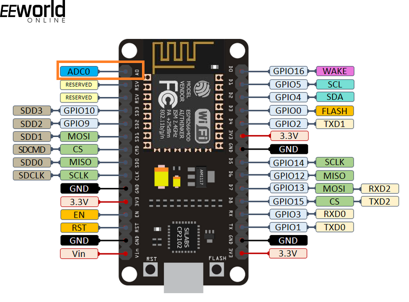
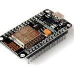
Analog input pins in ESP8266
For ESP8266, an ADC object can be instantiated in MicroPython using the ADC class. As there is only one analog input, the object must be defined using the following statement.
adc = ADC(0)
Only 10-bit resolution is allowed, so the ADC reading can be obtained only by calling ADC.read() method as follows.
adc.read()
Analog to digital conversion in ESP32
ESP32 has two SAR ADC peripherals. These peripherals are called ADC1 and ADC2. These are identified as ADC block 1 and ADC block 2. ADC1 has 8 ADC channels, and ADC2 has 10 ADC channels. The pins 32~39 are connected to ADC channels of ADC1 (block 1). The pins 0, 2, 4, 12, 13, 14~15, and 25~27 are connected to ADC channels of ADC2 (block 2).
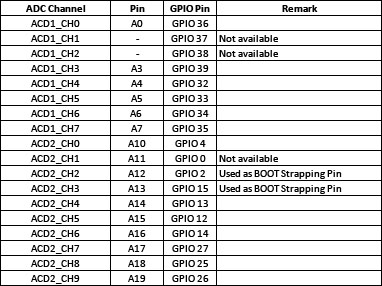
The default resolution of ESP32 ADC peripherals is 12 bits. Therefore, the read analog readings can range from 0 to 4095. However, the resolution of both ADC peripherals is configurable and can be set to a lower resolution like 10-bit, 9-bit or 8-bit. The analog input pins and the associated ADC channels in ESP32 are listed in the table below.
Both ADC and ADCBlock classes can be used for analog-to-digital conversion in ESP32. Either ADC or ADCBlock object must be instantiated for accessing ADC in ESP32. The resolution of the instantiated ADC channel can be set by calling ADC.width() or ADCBlock.init() methods. If the ADCBlock object is instantiated, it can be connected to either a channel or pin object. In ESP32, arbitrary connections between ADC channels and GPIO are not allowed. Therefore, ADCBlock.connect() method will not accept both parameters. If both arguments are passed, the ADCBlock.connect() will raise an error if the given ADC channel is not linked with the specified pin. The id in the ADCBlock() method can be 1 or 2, and the resolution can be 9~12. The ADC pins in ESP32 can tolerate voltages up to 3.3V. However, because the internal voltage reference is set to 1.1V, they can read analog voltages only up to 1.1V. The minimum voltage that both peripherals can detect is 100 mV. All voltages below 100 mV are read as 0. It is important to note that ADC2 is shared with the Wi-Fi, so the analog voltage from pins associated with ADC2 cannot be read if Wi-Fi is active.
The analog readings can be obtained by calling ADC.read() or ADC.read_uv() methods. Since the ADC peripherals of ESP32 read analog voltages below 100 mV as 0, the readings tend to be non-linear as they are close to the internal reference voltage, i.e., 1.1V, the ADC.read_uv() is recommended for obtaining ADC readings. If the ADC resolution is set to 11-bit or 12-bit, ADC.read_u16() method must be used.
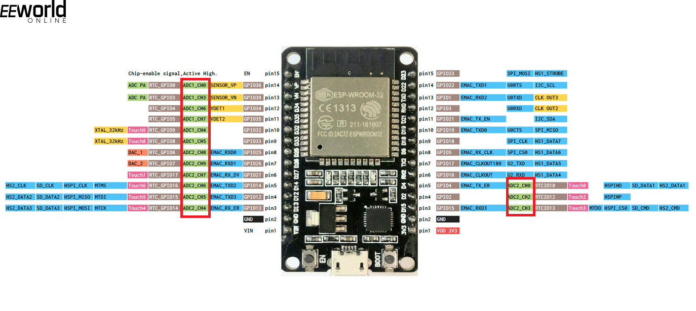
Analog input pins in ESP32
Controlling blink rate of LED with a potentiometer
Now equipped with the knowledge of ADC and ADCBlock classes of MicroPython and their application in ESP8266 and ESP32 boards, let us now design a simple application demonstrating the use of analog-to-digital conversion. In this application, we will control the blink rate of a LED by taking analog voltage as input from a potentiometer.
Components required
- ESP8266 x1
- 5mm LED x1
- 330Ω resistor x1
- 1K pot x1
- Breadboard x1
- Connecting wires/Jumper wires
Circuit connections
Connect GPIO5 of ESP8266 with the anode of the LED. Connect the cathode of the LED with a series resistor of 330 Ohms and ground the other terminal of the resistor. Take a potentiometer and connect fixed-end terminals 1 and 3 with ground and 3.3V, respectively. Connect the variable-end terminal 2 of the pot to analog input A0 of the ESP8266. The DC supply voltage and ground can be given to the circuit from the 3V3 out and one of the ground pins of the ESP8266, respectively.
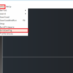
Note that MicroPython firmware must be already uploaded in ESP8266. Learn about uploading MicroPython firmware in ESP8266 and ESP32.
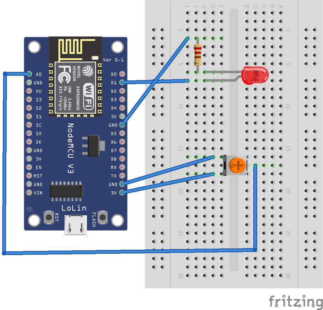
Circuit diagram for LED blink rate control using ESP8266 ADC
MicroPython script
from machine import Pin, ADC
from time import sleep
pot = ADC(0)
led = Pin(5, Pin.OUT)
while True:
pot_value = pot.read()
print(pot_value)
led.on()
sleep(pot_value/256)
led.off()
sleep(pot_value/256)
How it works
ESP8266 reads the analog voltage from a pot at its only analog input pin, A0. The read voltage is printed in the console of uPyCraft IDE. The same analog reading is divided by 256 and passed as a time interval between switching ON and OFF LED light.
The code
The code begins with importing Pin and ADC classes from the machine and sleep classes from the time modules. The ADC is initialized by calling the ADC() method, creating an ADC object called ‘pot’. The pin GPIO5 at which the LED is connected is set as a digital output by calling the Pin() method. In an infinite while loop, the ADC reading from the potentiometer is read by calling the read() method and is stored in a variable ‘pot_value’. The same value is printed to the console log by calling the print() function. The LED is switched ON by calling on the () method on the led pin object. A delay of pot_value/256 is invoked by calling the sleep() method. Then, the LED is switched OFF by calling off the () method on the led pin object, and the same delay is provided. This repeats endlessly, so the rate of LED blinking is controlled by the real-time analog input to ESP8266.
Result
You may also like:


Filed Under: Electronic Projects, ESP8266., Featured Contributions, Python, Tutorials

Questions related to this article?
👉Ask and discuss on EDAboard.com and Electro-Tech-Online.com forums.
Tell Us What You Think!!
You must be logged in to post a comment.