In the previous projects, the power source used was the AC mains. In this project, the solar energy will be tapped using a solar panel and it will be regulated to charge a 3.7 V battery. The 15 Watt solar panel used in the circuit has a DC output voltage of approximately 22 V. The DC output from the solar panel is not regulated and needs to be made ripple free using a voltage regulator. Once the voltage drawn from the solar panel is regulated to desired levels it can be utilized for powering load circuits. In the project, the regulated voltage is utilized to charge a battery.
The project involves deriving DC voltage from the solar panel, regulating input voltage, voltage adjustment, and back current protection. The LM-317 IC is used for the voltage regulation while a variable resistor is used for setting the output voltage to desired levels. The output voltage from LM-317 voltage regulator can be between 1.25V to 37V which is adjusted to 4.2 V which is suitable for charging a 3.7 V battery.
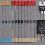
Components Required –

Fig. 1: List of Components required for Regulated Solar Energy Power Supply
Circuit Connections –
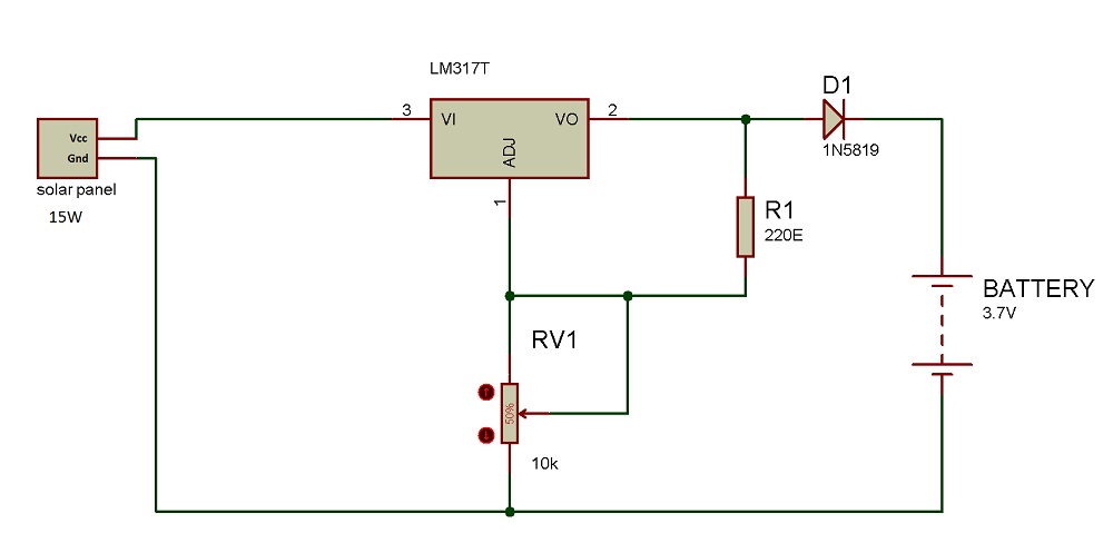
The 15-watt solar panel has two terminals VCC and ground which serve as indicated by their names. The VCC terminal of the panel is connected to the voltage input terminal of the LM-317 IC and the ground terminal is connected to a common ground. At the adjustment pin of LM-317 a variable resistor is connected and at voltage output pin of the regulator IC, a programming resistor R1 of 220 ohms is connected. A diode D1 with its anode connected to voltage output terminal of the regulator IC is connected in series to one of the output terminals of the circuit. The Voltage output terminal of LM-317 and common ground serve as the output terminals. A 3.7 V battery is connected to the output terminals for charging.
How the circuit works –
The functioning of the circuit can be broken down in the following operations –
1. Drawing DC Voltage from the solar panel
2. Voltage regulation
3. Voltage adjustment
4. Back current protection
Drawing DC Voltage from the solar panel
The solar panel is used to convert solar energy into electrical energy. The phenomenon of converting the solar energy to electric energy is called photovoltaic effect. This effect generates the voltage and current at the output on the exposure of solar energy. A 15 Watt 22 Volts Solar panel is used in the project. The panel has a voltage dropout of 2 to 2.75 V and maximum current output of 681 mA. The energy harnessed from the panel will be utilized to charge a 3.7 V 1000 mAHr battery. A solar panel consists of several solar cell or photovoltaic diodes. These solar cells are P-N junction diode and they can generate an electric signal in presence of solar light. On exposure to the sunlight, this solar panel generates a DC voltage output of 21 to 22 V at its terminals.

Fig. 2: Circuit Diagram of Solar Panel
Voltage Regulation
The voltage output from the solar panel is around 22V. it needs to be regulated to a smaller value for charging the battery. The 3.7V battery needs a voltage of 4.2V for its proper charging. The LM317 voltage regulator is used for regulating the voltage output of the solar panel.
LM317 is a monolithic positive voltage regulator IC. Being monolithic, all the components are inbuilt on the same semiconductor chip making the IC small in size having less power consumption and low cost. The IC has three pins – 1) Input pin where maximum 40 V DC can be supplied, 2) Output pin which provides an output voltage in the range of 1.25 V to 37 V and 3) Adjust pin which is used to vary the output voltage corresponding to the applied input voltage. For an input up to 40 V, the output can vary from 1.25 V to 37 V.
There is an In-built OPAM (Operational Amplifier) on the IC whose inverting input is connected with the adjustment pin. The non-inverting input is set by a band gap voltage reference whose voltage is independent of the temperature, power supply, and circuit loading. Therefore, LM317 gives a stable reference voltage of 1.25 V across its adjust pin. The reference voltage of 317 can be from 1.2 V to 1.3 V. The output voltage of 317 can be adjusted in a set range using a resistor divider circuit between the output and ground.
For setting the desired voltage at the output of LM317, resistive voltage divider circuit is used between the output pin and ground. By the effect of this configuration, the voltage at the output pin can be adjusted. The value of resistive voltage divider needs to be chosen in such a way that it can provide required voltage range at the output. The voltage divider circuit has a programming resistor which has a fixed resistance (Shown as R1 in schematics) and another is variable resistor (Shown as RV1 in schematics). By setting a perfect ratio of feedback resistor (fixed resistor) and variable resistor desired output voltage corresponding to the input voltage can be obtained.
For better performance of the IC, the fixed or programmable resistor R1 should be connected as close as to the regulator IC so that there is less line drop or less noise at the output. The RV1 must be connected near to the load ground for ground sensing and for improving the regulation.
The LM317 has the following internally tolerable power dissipation –
Pout = (Maximum operating temperature of IC)/ (Thermal Resistance, Junction−to−Ambient + Thermal Resistance, Junction−to−case)
Pout = (150) / (65+5) (values as per the datasheet)
Pout = 2 W
Therefore, LM317 internally can sustain up to 2 W power dissipation. Above 2 W, the IC will not tolerate the amount of heat generated and will start burning. This can cause a serious fire hazard also. So heat sink is needed to dissipate the excessive heat from the IC.

Fig. 3: Circuit Diagram of LM317 IC based Voltage Regulator for Solar Power Supply
Voltage Adjustment
For charging the 3.7 V Li-ion battery an input voltage of 4.2V is required. Therefore for setting 317 output voltage at 4.7V, RV1 must be set to the required position. By varying the RV1 output voltage between 1.1V and 10.4V can be obtained.
Back Current Protection
When there are no sun rays in the surrounding the solar panel has no voltage across it. At the output terminals, the battery still has some voltage across it which causes the output voltage to exceed than the input voltage (voltage from the solar panel). Therefore there is a reverse flow of current from the output to the input side and the battery starts discharging through the 317 regulator IC causing damage to it. By using a diode at the output, the reverse flow of current from the output terminal (battery) to the input terminal (solar panel) through 317 can be avoided so keeping the voltage regulator IC safe.

Fig. 4: Circuit Diagram of Back Current Protection
Testing and Precautions –
The following precautions should be taken while assembling the circuit –
• For driving high load current at the output, heat sink should be mounted at the holes of the regulator. This will prevent the regulator IC from blowing off. The 317 IC can internally handle power dissipation only up to 2W.
• The dropout voltage of LM317 IC is about 1.5V to 2.5V depending upon the output current. Therefore, the input voltage must be 1.5V to 2.5V greater than the desired output voltage.
• A diode (shown as D1 in schematics) should be used which takes less drop across it so that it does not reduce the output voltage. That is why 1N5819 diode that takes less drop across it is used.
• For driving high load the solar panel of high wattage rating should be used.
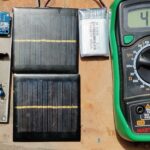
Once the circuit is assembled, measure the voltage and current readings using a multimeter. For charging a 3.7 V battery a voltage of 4.2 V is most suitable. The maximum current provided by the solar panel is given by –
Imax = Solar panel wattage/Solar Panel Voltage
Imax= 15/22
Imax = 681mA
With this current, the time required to charge the battery will be as follows –
Time taken for charging, T = 1Ah/0.681A = 1.46 hours (approximately)
The current by the 3.7V battery is 2mA. The current drawn by the battery depend on the charging status. It draws less current when it is fully charged.
Since the input voltage from solar panel is 22V and output voltage of the 317 regulator is 4.2V, the power dissipation across the regulator IC is derived as follows –
Preg = (Vin – Vout)*Ibatt
Preg = (22 – 4.2)*0.002
Preg = 35.6mW
Though the power dissipation of the regulator IC is found to be less than the internally tolerable limit of 2 Watts, still using a heat sink to aid cooling of the regulator IC and increase its life span is recommended.
The regulated solar power supply designed in this project provides regulated and adjustable voltage from 1.1V to 10.4V by varying the potentiometer RV1. Therefore any battery or load circuit that needs a voltage between 1.1V to 10.4V can draw power from this circuit. As this solar power supply provides maximum 681mA current, any battery or circuit which takes the maximum current of 681mA can be connected to it.
You may also like:


Circuit Diagrams
Project Video
Filed Under: Tutorials
Filed Under: Tutorials

Questions related to this article?
👉Ask and discuss on Electro-Tech-Online.com and EDAboard.com forums.
Tell Us What You Think!!
You must be logged in to post a comment.