This is bit little extension to previous 89C51 based DC motor controller. A digital speed indicator (seven segment displays) are connected to show speed variation. All other things remains same NOT gates, DC driver etc. Operation of 89C51 also changes as it will now work as serial data receiver.
I suggest you if you do not know how 89C51 controls DC motor then please click here to get an overview.
Transmitter:-
Controlling a DC motor means one can alter its two parameters speed and direction. So on remote control side only 5 switches out of 16 are used because 5 switches can perform most of the required functions. Please refer the table.
|
Switch |
Function |
|
SW1 |
Rotate motor clockwise |
|
SW2 |
Rotate motor anticlockwise |
|
SW3 |
Increase the speed of motor |
|
SW4 |
Decrease the speed of motor |
|
SW5 |
Stop the motor |
The operation remains same as explained before controller will generate and transmit a specific code every time when any key is pressed. So five different codes assign to each key and they are transmitted over IR channel when key is pressed.
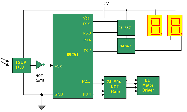
Receiver:-
The circuit diagram in its respective tab.
Connections:- As you can see main components are IR sensor (TSOP 1738), micro-controller 89C51, NOT gate IC74LS04, BCD to 7 segment decoder ICs 74LS47 and 7-segment displays (CA-Common Anode type) .
The inverted o/p of sensor is connected with RXD (P3.0) pin of microcontroller. Two 7-segment displays are connected to port P0 through 2 ICs 74LS47. They convert the BCD code given from micro-controller into corresponding 7-segment code and display it. DC Motor driver is connected to Port P2 pins through NOT gates. NOT gates simply work as buffer.
Operation:- IR sensor will demodulate 38KHz IR signal extracts the code and give it to micro controller.
Micro-controller is working as a serial data receiver. it will read the code and compare it and as the match found it will call that specific subroutine like start forward, start reverse, increase/decrease speed.
2-digit display indicates current speed (it’s a speed factor not actual RPM or RPS). When you increase or decrease speed by pressing key display will be changed.
1) On pressing key SW1 (or any other key) on remote control, it will generate and transmit standard code
2) This code will be demodulated by IR sensor and given to micro-controller. Micro-controller is continuously waiting for any code to arrive. When it receive the code it will switch to particular subroutine and start rotating motor clockwise. It also displays current speed on display.
3) Now if you press SW3 or SW4 same process will be executed and now micro-controller will increase/decrease speed of motor and also change display.
4) Pressing SW1/SW2 alternatively will rotate motor in both the directions alternatively. Speed remains unchanged.
Circuit Diagrams
Filed Under: Electronic Projects

Questions related to this article?
👉Ask and discuss on Electro-Tech-Online.com and EDAboard.com forums.
Tell Us What You Think!!
You must be logged in to post a comment.