Small organic light-emitting diode (OLED) displays are commonly used in embedded devices. This is because OLEDs generally cost the same as character LCDs but feature a better user interface (UI) and user experience (UX). Typically, embedded OLED screens are used to display textual messages, but what about videos? For example, is it possible to playback…
How to generate and display self made Custom characters on 16×2 lcd
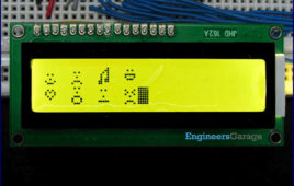
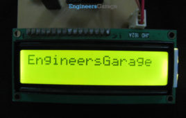
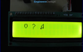
This tutorial is about making/building your own characters/special images and then displaying them on character 16×2 lcd. Generating custom characters or special character images and displaying on lcds of any sizes (16×1,16×2,8×1,8×2,20×1,20×2,40×1,40×2 etc) is not a very hard task. One must go through the internal structure of lcd control set in order to know how…
Insight – How an LED dot matrix display works
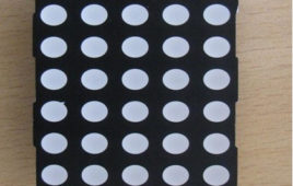
Light emitting diodes aligned in a form of matrix constitute a dot matrix display. It is commonly used to display time, temperature, news updates and many more on digital billboards. Dot Matrix Display is manufactured in various dimensions like 5×7, 8×9, 128×16, 128×32 and 128×64 where the numbers represent LEDs in rows and columns, respectively.Arrangement of the LEDs in the matrix pattern is made in either of the two ways: row anode-column cathode or row cathode-column anode. In row anode-column cathode pattern, the entire row is anode while all columns serve as cathode and vice-versa pattern is there in row cathode-column anode. LED wafers are glued to the bottom of the segments and glow when powered ON. The interesting part is that 35 LEDs are controlled by using a combination of 14 pins. Conductor tracks are laid all over the board to power each LED. Let’s proceed to know in depth about how a dot matrix display works.
How to identify and test the seven segment display?
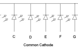
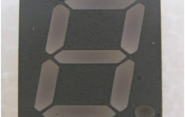
In 1910 Frank W. Wood made a board which can display number and after several modifications today it’s called 7-segment display. It is available in two configurations: common cathode and common anode. All the 8 LED terminals have their one end internally shorted and linked with the middle pins such that it serves as a common terminal (cathode or anode). 7 led are used to form the digits while the 8thone is for the dot which helps in identifying the correct orientation. It is widely used in digital clock, calculator, electronic meters and various other applications where numerical display is required. It can be used in place of dot matrix displays which are more complex than seven segment display. Seven segment displays can also be used to display some alphabets. Seven segment displays is a group of Light emitting diode (LED) arrange in figure of 8 pattern.
Random Number Generator Using 7 Segment Display
It is very simple and easy to construct project which will display random numbers from 0 to 7 on a 7 segment display. This circuit can serve as an alternative that can be used to replace the traditional dice while playing games such as snake ladder, monopoly etc. It uses NE555 which is a well known multivibrator IC. Here 555 timer IC is wired as an astable oscillator which provide a clock pulse to CD4017 IC.CD4017 which is a medium speed Johnson Counter that works at 10MHz and has 10 decoded outputs. CD4017 ICs are widely used in frequency dividers, binary counters, divide by N counters and register design applications and CD4511 which is a BCD to 7 segment decoder.
BCD to 7 Segment display Circuit
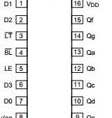
Many times we use LEDs in order to see binary outputs which are quite difficult to understand. The circuit described below will solve your problem as it will [[wysiwyg_imageupload::]]>display binary code on 7 segment displays, a very common and useful component of digital devices. It is based on CD4511, a CMOS BCD to seven segment latch/decoder and is used in various application like in clock, watches, computer, calculators etc. One thing to be kept in mind with this circuit is IC 4511 is used only for common cathode display. This IC provides the facility of 4-bit storage latch, an 8421 BCD-to-seven segment decoder. It also provides you the facility to check that all segments of 7 segment display are working properly or not (lamp test). For testing, momentarily make the pin low, in short used to test the display. Blanking input is used to turn off or vary the brightness of the display. Latch enable (LE) is used to store BCD codes.
Water level indicator with display
The water level indicator is used to measure the level of water present in the tank. This circuit not only indicates the amount of water present in overhead tank [[wysiwyg_imageupload::]]but it also gives an alarm when the tank is full. Water level indicator gives you an indication on 7 segment display by displaying E, P and C for empty, partially fill and completely fill, respectively.Water level indicator also gives you a display in the form of LED connected to it, you can also connect different color LED to distinguish the level of water present in it.The circuit is built around two IC’s namely 7408, 7404, 7 segment common cathode display and few more components. IC7408 is Quad two input AND gate and IC7404 is a hex inverting gate.
Displaying Regional Languages on LCD using Arduino
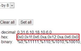
This project uses cheap Hitachi HD44780 based 16×2 LCD to display regional Indian language. These displays are designed for English text only, but they have [[wysiwyg_imageupload::]]provisions to display custom characters. On the LCD, each character is 8 pixels high by 5 pixels wide. Using a custom character designer, regional fonts were converted to hex codes, later to be used in the project. In order to understand the theory behind custom character generation we have to take a look at the memory mapping of HD44780.To display user information on regional language the characters need to be mapped onto a standard keyboard. In this case, the custom characters are mapped to a standard US-EN keyboard. When defining new character set, ASCII values of keys are assigned uniquely to each new custom character in ascending order [order is important as binary search is employed!]. Keep on reading to find out how the circuit is coded and how the connections are made.
How to create custom characters on 16×2 LCD using 8051 microcontroller (AT89C51)- (Part 10/45)
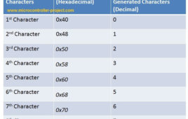
The commonly used 16×2 LCD can also display custom made characters besides numbers, alphabets & special characters. Any character can be made to appear on a 5×8 pixel matrix element without knowledge of its ASCII value. The idea explained here demonstrates the principle and operation of a simple LCD custom character display using 8051 microcontroller (AT89C51). When the ASCII code for any character, say ‘A’, is sent to be displayed on LCD module, the module’s controller looks up the appropriate 5×8-pixel pattern in ROM (read-only memory) and displays that pattern on the LCD. There are 8 symbol locations where a custom character can be stored as shown in the following right table. These locations will have a particular bitmap layout corresponding to the custom character. To display an arrow sign, the bitmap values are mapped to a base address location, say 64 (ASCII code 0).
CD 4060IC based Message Display Circuit
This simple message display can be used to display any message such as warnings, wishes, address notifications etc. as it will automatically turn ON at night or in [[wysiwyg_imageupload::]]dark. This circuit is based on CD4060 IC, LDR and few more components so that we can be easily made and can be gifted to friends. Here total of 12 bright LED glow inside the four segments (I through IV as shown in fig below) of the message plate to display different message. We can use bright white LED’s or different color LED’s to indicate different words. In this circuit, different segments glow for different duration of time. IC CD4060 is 14 stage ripple carry binary counter, divider and an oscillator. Its built in oscillator is main feature of this IC, so it can be used in numerous applications like flasher, clock generator in timer circuits. The resistance of LDR is very high in darkness, which reduces to minimum when LDR is in light.
Insight – How Scientific Calculator works
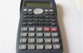
Scientific calculators are more of a habit for any engineer. Loaded with features that can solve complicated trigonometric, logarithmic and exponentia. The first scientific calculator was released in late 1960s by Hewlett Packard and numerous electronic manufacturers followed suit. Initially expensive and feature restricted, engineers have continually crammed more and more features into that little space as the semiconductor manufacturing industry continues to mature.Most of the scientific calculators, irrespective of the manufacturer, come in a hard plastic casing as shown above. The layout of the buttons is neat and ergonomic so that calculators can be used for long time without posing any risk of strain to the wrist and also ensuring correct key stroke each time, irrespective of the finger size pressing them.Let’s find out what makes this small sized gadget tick.
Voltage Level Display of 12V Battery
The voltage monitoring of a 12V battery is especially necessary when a discharged battery is being charged. It may be for the batteries used with inverters in home or commercial batteries. Here is a simple project produced to monitor the battery voltage using 741 op amp. The Circuit Diagram is shown in Circuit Diagram Tab.…
Multi-touch Screen Technology
While we are all fascinated by the touchscreen-market gimmick cajoling us with its ‘Touch away’ tagline, are we actually only at an inch’s distance? This ‘no-distance’ de facto makes sense at the front end only. When given a hawk’s eye, there is another world inside waiting to be discovered, waiting to satiate your knowledge for technology. Well, for the smart gadgets with smart people in the smart world, it’s an uncanny missing out a discussion on Touchscreen Technology, specifically undertaking the Multitouch Technology. The multi-touch or the plural touch is an interactive technique which allows users to interact with the digital environment inside the gadget, directly or indirectly with his fingers or palm. Multi-touch devices include smart phones, touch tables, computer tables, public kiosks, walls, and ‘touchpad’. Well these inverts in touchpad bring us to a minute line of demarcation between touchscreen and touchpad.
Computer Monitors – CRT, LCD, LED, Plasma & OLED Display Monitors
A computer monitor, technically termed as visual display unit is an output device that presents the information from the CPU on the screen working as an interface between CPU and the user. A cable connects the monitor to a video adaptor or video card which is set up on the motherboard of the computer. The CPU (Central Processing Unit) sends instruction to the video adaptor telling what needs to be displayed on the screen. The video adaptor converts the instructions into a set of corresponding signals and sends to the monitor. Monitor contains a circuitry that generates the picture on the screen from the set of signals. The major parameters that measure the performance of a monitor are luminance, contrast ratio, resolution, dot pitch, response time, refresh rate and power consumption. The common problem that arises in monitors is dead pixels, blurred screen, phosphor-burn, etc.
Insight – How Seven Segment Display works
In 1910 Frank W. Wood made a board which can display number and after several modifications today it’s called7-segment display. 7 segment display is a 10 [[wysiwyg_imageupload::]]pin electronic component with eight led’s embedded inside it to displays number from 0 to 9.It is available in two configurations: common cathode and common anode. All the 8 LED terminals have their one end internally shorted and linked with the middle pins such that it serves as a common terminal (cathode or anode). Middle pin of both sides are shorted with each other which serves as a common terminal. 7 led are used to form the digits while the 8thone is for the dot which helps in identifying the correct orientation. Read more to find out how internal features of 7-segment display and know how it works.
Moving LED Display
Moving LED Display is very active application of digital electronics. The application of this device can be found everywhere. From name plate display to train number display this display is used. The power consumption is 70% less than primitive display. The main advantage of using this display is the information displaying on the display can easily be change by changing the program in microcontroller. And also animation is possible during displaying the massage. This is undoubtedly acceptable in the high society. There is another advantage of this device i.e. less cost-effective. The LED used in this device is RED LED having wavelength 660nm. Hence the displaying massage can be seen from very high distance.
How to interface 16×2 LCD in 4-bit mode with PIC Microcontroller (PIC18F4550)- (Part 7/25)
The 16×2 character LCD can work in two modes, namely, 8-bit and 4-bit. These modes basically correspond to the number of data pins used in interfacing LCD. 8-[[wysiwyg_imageupload::]]bit mode uses all the data lines and has been explained in LCD interfacing with PIC18F4550. In 4-bit mode, only four data pins of LCD are connected to the controller. This mode, thus, saves four pins of the controller unlike 8-bit mode. The configuration and display method of LCD in 4-bit mode has been explained here. The 8-bit mode of LCD interfacing with PIC has been explained earlier. In the 4-bit mode the (8-bit) data/command is sent in nibble (four bits) format to LCD. The higher nibble is sent first followed by the lower nibble. In 4-bit mode only four data pins (D4-D7) of LCD are connected to the controller. The control pins (RS, RW and EN) are connected the same way as in 8-bit mode.
How to create custom characters on 16×2 LCD using PIC18F4550- (Part 8/25)
The 16×2 character LCD can also be used to display custom characters other than numerals, alphabets & special characters. Refer LCD interfacing with PIC. Some [[wysiwyg_imageupload::]]special shapes like hearts, arrows, smileys etc. can easily be displayed on the 5×8 pixel pattern of character LCD. These shapes are first stored at a special location in LCD’s controller and then displayed on the LCD module. This procedure has been explained here by using PIC18F4550. The special characters are generated by bit-mapping of LCD’s 5×8 bit pixel matrix. Refer Creating custom characters on LCD using 8051 for more details on bitmap generation and storing custom values in custom generator (CG) RAM of LCD’s controller. The mikroC IDE provides LCD Custom Character tool to create the bitmap of user defined custom character. Read further to know how are the characters created.
How to display an image on Graphics LCD using AT89C52- (Part 45/45)
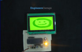
The Graphics LCD as the name suggests is a type of LCD which can display graphics. The graphical representation of any data presents good understanding thanjust characters. More user friendly applications can be designed by using the graphical LCDs. The graphical LCD can be used for advertisement boards or information boards and so on. This article explains the method of displaying image on a 128×64 graphical LCD using AT89C52. For basic operations and working, refer Graphics LCD interfacing with 8051. Microcontroller AT89C52 has been used to control the operations of the graphical LCD. The Graphics LCD used here is JHD12864E. This LCD is divided into two parts which are controlled by two different controllers. Each of these parts is divided into rows and columns. For basic instructions and programming procedure, refer to interfacing Graphics LCD with 8051. Also see displaying text on Graphics LCD. Read more to make interesting graphics on this florescent piece of display.
How to interface LED with AVR Microcontroller (ATmega16)- (Part 4/46)
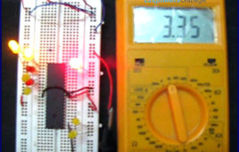
ATmega16 has 32 I/O pins to communicate with external devices. Before interfacing with external devices, these pins must be cofigured as input or output pin. [[wysiwyg_imageupload::]]This article demonstrates the basic I/O operation of ATmega 16 using LEDs. All the four ports can be configured to read an input from some external device or to give output to any external device as per the application. For e.g., a switch is connected to a particular pin, that pin should be configured as input to read the values from the switch (external Device in this case) and if you are connecting a LED to any pin of the port then that particular pin should be configured as output to transmit the signal to the LED (external device in this case). A single port can be configured such that some of the pins of the same port are input and some are output. Read on more to understand how LED interfacing is done with the help of an AVR.

