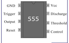
IC 555 timer is a well-known component in the electronic circles but what is not known to most of the people is the internal circuitry of the IC and the function of various pins present there in the IC. Let me tell you a fact about why 555 timer is called so, the timer got its name from the three 5 kilo-ohm resistor in series employed in the internal circuit of the IC. IC 555 timer is a one of the most widely used IC in electronics and is used in various electronic circuits for its robust and stable properties. It works as square-wave form generator with duty cycle varying from 50% to 100%, Oscillator and can also provide time delay in circuits. The 555 timer got its name from the three 5k ohm resistor connected in a voltage-divider pattern.
Simple DC Motor Controller using 555 Timer IC
Controller is actually a combination of two circuits – driver circuit and Switching circuit. Driver is the actual circuit that drives DC motor and switching circuit decides how DC motor should be driven. So actually, switching circuit is the main circuit that controls the motor. Now there are two parameters of DC motor that can be controlled Speed and Direction.Changing the direction of DC motor is very simple just reverse the supply given to DC motor. For varying speed of motor you have to vary the applied DC voltage. One well known method widely used in industries is Pulse Width Modulated (PWM) speed control of DC motor also known as chopper control.
DIY : Short Range Optical Pulse Transmitter and Receiver
This project demonstrates how pulses can be transmitted from one place to another place wirelessly using light as medium. One LED is connected at the transmitter side that blinks at frequency of applied pulses. At the receiver side, Light Dependent Resistor (LDR) is used to receive light pulses. IC555 is used at both ends. At transmitter side it is used to generate continuous pulses with variable frequency output from 1 Hz to 10 Hz. At receiver side it is used to generate same pulses as per the trigger input applied by LDR. Note – for visual effect (demonstration) the pulse frequency is kept low. The frequency can be kept high in terms of KHz also.
Simple DC Motor Controller using 555 Timer IC
Controller is actually a combination of two circuits – driver circuit and Switching circuit. Driver is the actual circuit that drives DC motor and switching circuit decides how DC motor should be driven. So actually, switching circuit is the main circuit that controls the motor. Now there are two parameters of DC motor that can be controlled Speed and Direction.Changing the direction of DC motor is very simple just reverse the supply given to DC motor. For varying speed of motor you have to vary the applied DC voltage. One well known method widely used in industries is Pulse Width Modulated (PWM) speed control of DC motor also known as chopper control.
Interfacing 3-Axis Accelerometer with 8051 Microcontroller
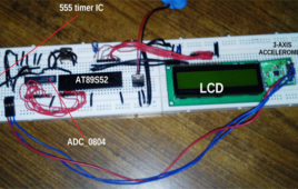
This project involves various stuffs like accelerometer module, 8 bit ADC, 555 timer IC, LCD display etc. So I’ll be discussing about all of them step by step. First let’s talk about the Accelerometer IC; here I have used ADXL_335 which is a 3-axis accelerometer module. This module provides X, Y and Z axis data.


