Engineers Garage

  • Projects and Tutorials
    • Electronic Projects
      • 8051
      • Arduino
      • ARM
      • AVR
      • PIC
      • Raspberry pi
      • STM32
    • Tutorials
    • Circuit Design
    • Project Videos
    • Components
  • Articles
    • Tech Articles
    • Insight
    • Invention Stories
    • How to
    • What Is
  • News
    • Electronic Products News
    • DIY Reviews
    • Guest Post
  • Forums
    • EDABoard.com
    • Electro-Tech-Online
    • EG Forum Archive
  • Digi-Key Store
    • Cables, Wires
    • Connectors, Interconnect
    • Discrete
    • Electromechanical
    • Embedded Computers
    • Enclosures, Hardware, Office
    • Integrated Circuits (ICs)
    • Isolators
    • LED/Optoelectronics
    • Passive
    • Power, Circuit Protection
    • Programmers
    • RF, Wireless
    • Semiconductors
    • Sensors, Transducers
    • Test Products
    • Tools
  • EE Resources
    • DesignFast
    • LEAP Awards
    • Oscilloscope Product Finder
    • White Papers
    • Webinars
  • EE Learning Center
  • Women in Engineering

Simple DC Motor Controller using 555 Timer IC

By Ashutosh Bhatt

Controller is actually a combination of two circuits – driver circuit and Switching circuit. Driver is the actual circuit that drives DC motor and switching circuit decides how DC motor should be driven. So actually, switching circuit is the main circuit that controls the motor. Now there are two parameters of DC motor that can be controlled Speed and Direction.

Changing the direction of DC motor is very simple just reverse the supply given to DC motor. For varying speed of motor you have to vary the applied DC voltage. One well known method widely used in industries is Pulse Width Modulated (PWM) speed control of DC motor also known as chopper control.


Controller is actually a combination of two circuits

Controller    =    Driver    +    Switching circuit

Driver is the actual circuit that drives DC motor and switching circuit decides how DC motor should be driven. So actually, switching circuit is the main circuit that controls the motor. Now there are two parameters of DC motor that can be controlled 

1. Speed

2. Direction

Changing the direction of DC motor is very simple just reverse the supply given to DC motor.            

For varying speed of DC motor you have to vary the applied DC voltage. One well known method widely used in industries is Pulse Width Modulated (PWM) speed control of DC motor also known as chopper control. In this method PWM is applied to DC motor and as the width of pulse varies average voltage applied to motor varies and so the speed of motor also varies.  

In this project I have used standard H-Bridge circuit as a DC motor driver and astable multvibrator (using IC-555) as a PWM generator. IC-555 generates PWM with the base frequency of 100 Hz. This PWM is applied to H-Bridge driver through DPDT switch which decides direction of rotation either clockwise or anticlockwise.

The DC motor controller that I have given here can be used in controlling small or medium DC motors of Drilling machine, portable DC fan, small water pump etc.

Simple DC Motor Controller using 555 Timer IC

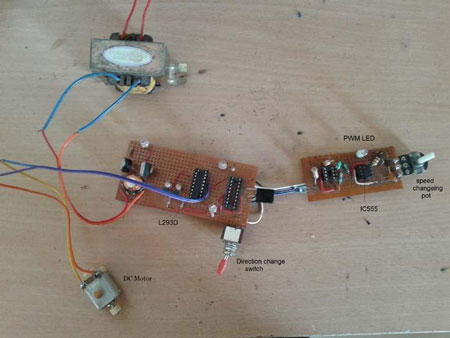
Fig. 1: Prototype of 555 IC based DC Motor Speed Controller

 Block Diagram & Circuit Description

Block Diagram:-

DC Motor Control Block Diagram

Fig. 2: Block Diagram of 555 IC based DC Motor Speed Controller

As we already stated there are only two main blocks in our project one is PWM generator and other is H-Bridge DC Motor driver. Regulated 5 volt supply is used as source for whole circuit.

The PWM generator generates PWM with 100 Hz base frequency. It is fed to H-bridge driver through switches. One DPDT is used for selecting direction of rotation either clockwise or anticlockwise.

Circuit Description:

The main components are IC555, DPDT switch (double pole double through) and motor driver chip L293D. The heart of the circuit is IC-555.

Connections: – IC555 is connected in astable mode and it’s frequency is determined by R1, pot R2 and C1. Pot R2 is used to vary pulse width of output waveform. Output of IC-555 (Pin no. 3) is connected to terminals 1 and 4 of DPDT switch as shown. One LED is also connected to IC555 output through current limiting resistor. Terminals 2 and 3 of DPDT switch are connected to ground. Terminals 5 and 6 of switch are connected to 2 inputs of L293D chip. DC motor is connected to two outputs of L293D. Entire circuit works on single 5 V supply.

Operation:-

  • IC-555 is connected in astable mode so it will generate a rectangular wave at its output pin. The frequency of this wave depends upon the component values of R1, R2 and C1 and it is 100 Hz (time period 10 ms). Because of its typical connection as you vary the pot R2 the width of the pulse varies but the frequency remains constant. You can vary the width of the pulse from min 1 ms to max 9 ms in the period of 10 ms. The waveforms given below will give you clear idea.
  • This PWM is given to LED. So as PWM width increases LED intensity increases and vice versa.
  • The DPDT switch is on position 1 and 3. So IP1 of L293D chip is connected with IC555 output and IP2 is connected to ground. This will start rotating motor in one direction. If you change potentiometer then PWM width changes and DC motor speed changes. Also LED intensity changes
  • When DPDT switch position is changed to 2 and 4 the connection reverses. Now IP2 connects to IC555 output and IP1 connects to ground. This makes motor rotates in another direction.
  • Thus as you change switch position motor changes its direction and as you change potentiometer from min to max the motor speed will change from min to max.
  • DC Motor SpeedFig. 3: Signal Diagram showing PWM for DC Motor Speed Control


Circuit Diagrams

DC-Motor-Controller-Circuit_0


Filed Under: 555 Timers, Electronic Projects
Tagged With: 555 timer circuit, 555 timer IC, dc motor, speed control
 

Questions related to this article?
👉Ask and discuss on EDAboard.com and Electro-Tech-Online.com forums.


Tell Us What You Think!! Cancel reply

You must be logged in to post a comment.

HAVE A QUESTION?

Have a technical question about an article or other engineering questions? Check out our engineering forums EDABoard.com and Electro-Tech-Online.com where you can get those questions asked and answered by your peers!


Featured Tutorials

  • Designing Gate Driver Circuit and Switching Mechanism for Modified Sine Wave Inverter – (Part 9/17)
  • Completing Modified Sine Wave Inverter Design with Full Bridge Circuit and Step Up Transformer – (Part 10/17)
  • Designing an Offline UPS – Part (12 /17)
  • How to reduce Switching Time of a Relay – (Part 15/17)
  • Testing MOSFET – (Part 16/17)
  • Driving High Side MOSFET using Bootstrap Circuitry – (Part 17/17)

Stay Up To Date

Newsletter Signup

Sign up and receive our weekly newsletter for latest Tech articles, Electronics Projects, Tutorial series and other insightful tech content.

EE Training Center Classrooms

EE Classrooms

Recent Articles

  • Renesas to demonstrate first working silicon based on the Arm Cortex-M85 processor
  • STMicroelectronics releases first automotive IMU with embedded machine learning
  • Infineon offers DC-DC controller for full LED headlamps without a microcontroller
  • Vishay launches new high-precision, thin-film wraparound chip resistor
  • STMicroelectronics’ common-mode filters ensure signal integrity in serial interfaces

Most Popular

5G 555 timer circuit 8051 ai Arduino atmega16 automotive avr dc motor display Electronic Part Electronic Parts Fujitsu ic infineontechnologies integratedcircuit Intel IoT ir lcd ldr led maximintegratedproducts microchip microchiptechnology Microchip Technology microcontroller microcontrollers mosfet motor powermanagement Raspberry Pi remote renesaselectronics renesaselectronicscorporation Research samsung semiconductor sensor software STMicroelectronics switch Technology vishayintertechnology wireless

RSS EDABOARD.com Discussions

  • Temperature sensor readout
  • Capacitive Switches
  • CSI-2 FIFO or Line buffer?
  • What is the function of the long stub?
  • Circuit Performance Exploration

RSS Electro-Tech-Online.com Discussions

  • software PWM
  • Opamp ciruit
  • Audio equalizer
  • Background of Members Here
  • SPI Questions
Engineers Garage
  • Analog IC TIps
  • Connector Tips
  • DesignFast
  • EDABoard Forums
  • EE World Online
  • Electro-Tech-Online Forums
  • Microcontroller Tips
  • Power Electronic Tips
  • Sensor Tips
  • Test and Measurement Tips
  • 5G Technology World
  • About Us
  • Contact Us
  • Advertise

Copyright © 2022 WTWH Media LLC. All Rights Reserved. The material on this site may not be reproduced, distributed, transmitted, cached or otherwise used, except with the prior written permission of WTWH Media
Privacy Policy | Advertising | About Us

Search Engineers Garage

  • Projects and Tutorials
    • Electronic Projects
      • 8051
      • Arduino
      • ARM
      • AVR
      • PIC
      • Raspberry pi
      • STM32
    • Tutorials
    • Circuit Design
    • Project Videos
    • Components
  • Articles
    • Tech Articles
    • Insight
    • Invention Stories
    • How to
    • What Is
  • News
    • Electronic Products News
    • DIY Reviews
    • Guest Post
  • Forums
    • EDABoard.com
    • Electro-Tech-Online
    • EG Forum Archive
  • Digi-Key Store
    • Cables, Wires
    • Connectors, Interconnect
    • Discrete
    • Electromechanical
    • Embedded Computers
    • Enclosures, Hardware, Office
    • Integrated Circuits (ICs)
    • Isolators
    • LED/Optoelectronics
    • Passive
    • Power, Circuit Protection
    • Programmers
    • RF, Wireless
    • Semiconductors
    • Sensors, Transducers
    • Test Products
    • Tools
  • EE Resources
    • DesignFast
    • LEAP Awards
    • Oscilloscope Product Finder
    • White Papers
    • Webinars
  • EE Learning Center
  • Women in Engineering