This project is about interfacing RF (Radio Frequency) module with the 8051 microcontroller. These RF 1modules help us in sending and receiving the data wirelessly up to certain distance. This provides us the ease of wireless data transferring. There are many forms of wireless technologies which can transfer the data such as Bluetooth modules, ZigBee modules, and Wi-Fi modules.RF is one of them. It’s a lot cheaper and works quite well for small scale projects. These modules are really easy to deal with. They jus1t require the data to be transferred serially and VCC+GND supply of course.
How to make a cheap robotic arm
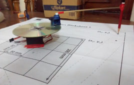
Recently I joined an MOOC on Introduction to Robotics by Queensland University of Technology, Australia. For those who don’t know what MOOC is, it stands for Massive Open Online Course. Professor Peter Corke was the mentor in introducing me to the world of robotics. Apart from the learning side of this course there was an optional project on building one’s own robotic arm which could track a given path provided by them.
Controlling a BLDC Motor with an ESC
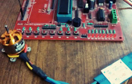
Brushless motors have much more satisfying results as compared to brushed motors. The basic difference between them is that in a brushless motor, the rotor itself contains the permanent magnets and the electromagnets move to the stator which is quite opposite as seen in a brushed motors. It’s more precise and can also factor the speed of the motor into the equation. This makes brushless motors more efficient. There is no sparking and much less electrical noise. There are no brushes to wear out. With the electromagnets on the stator, they are very easy to cool. You can have a lot of electromagnets on the stator for more precise control. The only disadvantage of a brushless motor is its higher initial cost, but you can often recover that cost through the greater efficiency over the life of the motor.
Keypad Locking System with User Defined Password
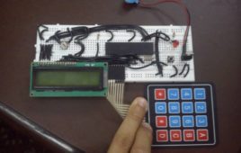
In this keypad lock project I have used the AT89S52 microcontroller, one of the series of 8051 microcontroller by ATMEL corp. Here I’m using 4X4 keypad to take input from the user (to enter password) and display the corresponding results on a 16X2 LCD. Since AT89S52 doesn’t have its own internal oscillator, thus we need to provide an external crystal of 11.0592 Mhz to make it function able. I am using a 7805 voltage regulator IC to convert 9V to desired 5V output.
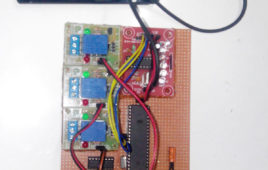
Controlling Appliances Wirelessly using RF Technology
Now a day’s everyone needs a device which could control appliances wirelessly. This makes us to operate them on our fingertips from particular vicinity with ease.This time I have done something like this, I have created a prototype of a device which controls 4 devices/appliances separately using RF (Radio Frequency) technology. The device comprises of two sections: Transmitting (remote) and Receiving part. The transmitting part works as a remote device to send the corresponding data to the receiver section. It further consists of 4 SPDT (single pole double throw) switch, one Encoder IC (HT12E) and a TX module (433 MHz). These 4 switches are connected to the 4 data pins of the encoder IC to generate a 4-bit data to be transmitted. The switches provide either high (+5V) or low (0V) signal levels.
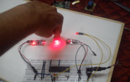
DIY Game: Glow All the LEDs First!
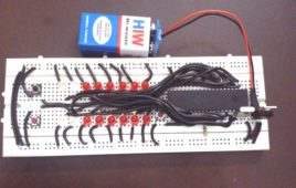
This is a 2 player game, based on 8051 microcontroller AT89S52. This game features two push buttons (one for each player) and an array of 8 LEDs for each. It demands high reflexes, as you have to push button as fast as you can. Each press would help the successive LED to glow until all the 8 LEDs are on. The competition is about how fast you can toggle (Press and then un-press) the buttons, greater your speed of pressing push button, greater will be your chance of winning. As soon as any of the two players reach the last LED, the push button of another player will get deactivated, which means it will not respond to the push. Also the LEDs of the winner will start toggling. This will ensure the accurate after results. To restart the game, press the reset button (button connected to pin 9 on microcontroller).
Interfacing triple-axis accelerometer with AtMega16
This project makes use of three out of the eight ADCs present in AtMega16 IC to display the corresponding digital data of X, Y and Z outputs of an accelerometer on 16X2 LCD.It’s very easy to deal with such kind of modules as they just need the VCC and GND supply to get started, rest it is its job to provide us the analog data.These modules work on simple concept like that of force acting on an object at inclined plane. It deals with the Mg(sin ?) and Mg(cos ?) part of the force and calculate the angle ? for further calculations. Now it also notices the change in force from which acceleration will be calculated.
Mobile-controlled robot

Mobile controlling is done mainly with DTMF decoder. DTMF stands for Dual Tone Multi Frequency. This module can take up-to 4 bits of data at a time (i.e. 0-15 decimal values).DTMF needs two mobile platforms, one for sending instructions while another for receiving them. This module contains a IC which decodes the signals received and convert it into 4 bit data.
Fastest Finger First (without microcontroller or IC)

I heard about this term “Fastest Finger First” in the show “Kaun Banega Carorepati” hosted by very famous legend “Mr. Amitabh Bachchan” and I think most of you are aware of that. But the interesting part of that show for me was when fastest finger first was played between the contestants. I always wondered whether I can build stuff like that. Then in my school period I was given a job to create a buzzer system which could detect which one of the 4 contestants pressed it first. I implemented it in a quiz at my school and it worked damn awesomely. It took me quite a time to think on how I am going to create this because at that time I did not have the knowledge of microcontrollers. My dad who’s an electrical engineer helped me with the basic idea of using relays (thank you dad). From then I started imagining on what kind of circuit to make so that it works accordingly. The CIRCUIT DIAGRAM that you can see above is what came out as a result of my hard work. I know it’s a bit complicated but seriously telling you guys this thing makes me proud of myself. Okay let’s stop this story here and move toward its description. Do watch the circuit above and for your ease I have given a unique colour to very wire associated with individual relay.
Fingerprint Detection using Microcontroller- (Part 45/46)

In today’s secure world biometric safety is on the top. Unlike other techniques which make use of passwords and numbers, that are needed to be remembered, biometric techniques make use of human body parts like fingerprints or even iris of your eyes and as we know that these things are unique to all thus it makes biometric systems the most effective over others. In this project I have interfaced a very popular fingerprint scanner R305 with AtMega 16 microcontroller. This module communicates over UART protocol with microcontroller i.e. it makes use of Rx and Tx pin of microcontroller to interact with it.
Mobile – Gesture Controlled Car

Have you ever wondered of operating a toy car with you own mobile phone? Yes I have made such a thing. This project involves the communication between your mobile phone and the car. Here I have used the internal accelerometers of the mobile phone to operate my toy car.The system communicates wirelessly over Bluetooth interface, thus we require a phone with Bluetooth compatibility. Moreover I have made an Android Application for the same task therefore the phone must have ANDROID operating system J
Sleeping Security – Smart Keypad Lock using AtMega16
This project is just a smart version of any keypad lock. What’s smart about it is that it can detect whether it is needed by the user or not and accordingly switches itself to take a sleep. Making a microcontroller to sleep reduces power consumption as well as increases its usage span.Many of you must be wondering that would it be secure enough to make a lock go to sleep, isn’t it. Don’t worry, when a microcontroller goes off to sleep it puts a hold on what it was doing before sleeping. In my project I have made it to sleep only when the user has finished entering the password stuff and microcontroller has done its entire job.
Mobile Controlled Home Automation
This project uses DTMF technology to control home appliances. DTMF stands for Dual Tone Multi Frequency.This DTMF based system can control home appliances via mobile phone communication from anywhere around the world.This facilitates the user to operate anything on his fingertips.It requires two cell phones to operate properly; one of them will always remain in touch with the circuit and another to place a call on that phone.
Lasered Security System
This system for security uses the combination of LASER light and LDR. The LDR module has an onboard potentiometer to adjust the sensitivity of LDR, so that it only senses laser light falling onto it.The concept is quite simple and similar to what we see in movies where antique, priceless ornaments are protected under laser lights.As someone crosses these lights, an alarm runs on to indicate unauthorised presence. This project works similarly.In normal conditions, where there is always laser light falling on the LDR, the LDR module always gives a high signal to microcontroller
Line Follower Robot

Line follower robot is a bot which can follow a particular line. Its a very good project to start with, for people who are interested in robotics and embedded systems.In this case, it will follow a black line on a contrasting white background surface.This bot comprises of a sensor section, driver section and a microcontroller to process the sensor values and correspondingly operate the motor driver section.Sensor section consists of IR sensors (2 in this case)Driver section involves the working of geared DC motors (via L293D IC)
16-Channel Data Acquisition System(DACQ)
1) Introduction Data acquisition systems, as the name of this system implies, are processes used to assemble information to paper or analyze some phenomenon. In the simplest form, a technician logging the temperature of an oven on a piece of paper is performing data acquisition. As technology has progressed, this type of process has been…
DC Motor Control using PWM with ADC
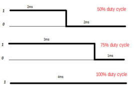
This project involves a combination of PWM (pulse width modulation) and ADC (Analog-Digital converter) to drive a DC motor at various speeds and in both clock and anti directions.PWM is a concept with which one can modify the pulse voltage varying it from 0% duty cycle to 100%.Duty cycle represents the time for which pulse is high when compared to the full pulse length.
AC Dimmer

We all know what an AC dimmer is; for those who don’t, it’s a kind of a circuit which can control the amount of AC voltage to be given to any device. You can see them in a fan regulator or a light dimmer switch. But have you ever wondered of applying the same concept of regulators/dimmers using a microcontroller? If you haven’t, don’t worry, this project deals with the same stuff.First of all we need to understand the importance of a triac in such circuits. A triac is a 3 terminal device which can control the amount of AC current passing through it. This can be achieved by applying variable AC potential at its Gate pin.
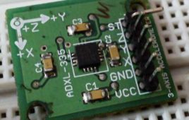
Interfacing 3-Axis Accelerometer with 8051 Microcontroller
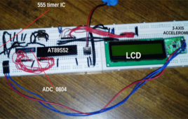
This project involves various stuffs like accelerometer module, 8 bit ADC, 555 timer IC, LCD display etc. So I’ll be discussing about all of them step by step. First let’s talk about the Accelerometer IC; here I have used ADXL_335 which is a 3-axis accelerometer module. This module provides X, Y and Z axis data.
Interfacing L293D with 8051 Microcontroller
L293D is a motor driver IC. As its name suggests it can drive a motor (normally DC motors up-to certain range). Since the output voltage of 8051 is limited to 5V only thus motors with higher required voltage need some drivers to provide them their desired input voltage.What L293D does is, it takes the TTL (0/5v) input from the output pins of 8051 microcontroller and forwards the output through itself of higher voltage(required by DC motors).Connecting a DC motor directly to the pins of 8051 would not work. It may even damage the microcontroller. L293D is a 16-pin IC which can control a set of two DC motors simultaneously in any direction. It means that you can control two DC motor with a single L293D IC.