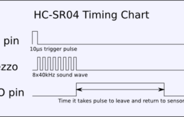
HC-SR04 based Distance Finder gives the distance from an obstacle in centimetres. It has a range of 2cms to 400cms. The project is build around AT89S52 which 8051 based microcontroller. The distance is displayed on Seven Segment Displays.The working of the ultrasonic sensors is quite simple and they are easy to interface with the microcontroller. The sensor module has 4-pins out of which Pin-1 and Pin-4 are +Vcc and Gnd respectively.Pin-2 is Trigger and Pin-3 is Echo pin.When a High pulse of 10us is applied at TRIG pin, the ultrasonic transmitter sends 8 consecutive pulses of 40kHz frequency. As the Eighth pulse is sent the ECHO pin of the sensor becomes HIGH. Now when the ultrasonic waves reflect from any surface and are received by the Receiver, the ECHO pin becomes LOW.
Keypad Locking System with User Defined Password
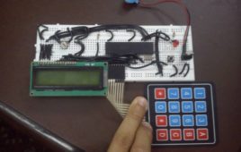
In this keypad lock project I have used the AT89S52 microcontroller, one of the series of 8051 microcontroller by ATMEL corp. Here I’m using 4X4 keypad to take input from the user (to enter password) and display the corresponding results on a 16X2 LCD. Since AT89S52 doesn’t have its own internal oscillator, thus we need to provide an external crystal of 11.0592 Mhz to make it function able. I am using a 7805 voltage regulator IC to convert 9V to desired 5V output.
Real Time Clock with Alarm Option using AT89S52 and DS1307 IC
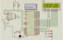
Real time clock is a digital clock which display real time on 16×2 LCD display. Here in this circuit we can also set alarm and time. The DS1307 serial real-time clock (RTC) is a low-power, full binary-coded decimal (BCD) clock/calendar plus 56 bytes of NV SRAM. Address and data are transferred serially through an I²C, bidirectional bus.The clock/calendar provides seconds, minutes, hours, day, date, month, and year information. The end of the month date is automatically adjusted for months with fewer than 31 days, including corrections for leap year. The clock operates in either the 24-hour or 12-hour format with AM/PM indicator.
Mobile-controlled robot
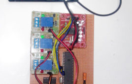
Mobile controlling is done mainly with DTMF decoder. DTMF stands for Dual Tone Multi Frequency. This module can take up-to 4 bits of data at a time (i.e. 0-15 decimal values).DTMF needs two mobile platforms, one for sending instructions while another for receiving them. This module contains a IC which decodes the signals received and convert it into 4 bit data.
Wireless monitoring and controlling rescue robot using Zigbee
The robot is operated through PC using wireless technology using zigbee and using wireless camera we can view both audio and video on the TV. This robot has a high power LED which acts as a light source when light intensity inside the pipe is low .It is a low cost robot used to monitor the changes of different parameters in the industrial pipes. By connecting temperature sensor to the robot we can get the temperature of dangerous zones in PC itself. By connecting smoke sensor to the robot we can get the information related concentration of smoke or gases in respective fields.
Mobile Controlled Home Automation
This project uses DTMF technology to control home appliances. DTMF stands for Dual Tone Multi Frequency.This DTMF based system can control home appliances via mobile phone communication from anywhere around the world.This facilitates the user to operate anything on his fingertips.It requires two cell phones to operate properly; one of them will always remain in touch with the circuit and another to place a call on that phone.
Line Follower Robot
Line follower robot is a bot which can follow a particular line. Its a very good project to start with, for people who are interested in robotics and embedded systems.In this case, it will follow a black line on a contrasting white background surface.This bot comprises of a sensor section, driver section and a microcontroller to process the sensor values and correspondingly operate the motor driver section.Sensor section consists of IR sensors (2 in this case)Driver section involves the working of geared DC motors (via L293D IC)
Tachometer using microcontroller
Here is a trial of building a tachometer using AT89S52 Microcontroller. This is a digital tachometer which works using infrared rays. The tachometer designed here can measure rotational speed up to 4200 rpm which is sufficient for small scale use. If the speed goes beyond 4200 rpm, it gives a message on the display screen as “OUT OF RANGE”.Take out the wheel of a damaged optical mouse and make a hole at the center of the wheel. Put the steel rod at the hole and glue it tightly so that the rod and the wheel rotate simultaneously. Make the plywood frame as shown in figure and screw the screw bearings on both sides so that the rod with the wheel can be mounted. After mounting the rod (with the wheel) on the screw bearings, try rotating the wheel with your finger. While rotating, the rod should have a minimum friction with the screw bearings.
Controlling Audio Volume & Tone with a Remote Control
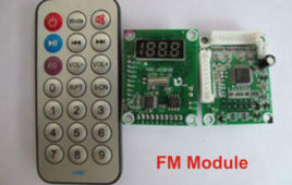
Here is the project of controlling audio volume and audio tone (bass and treble) with a remote control designed using microcontroller AT89S52.It is a mono audio controller and to make it stereo similar circuits have to be made for the both LEFT and RIGHT channels. I have not connected the components in a PCB…
Controlling a Desktop Computer with a Remote Control
Here is the project of controlling a desktop computer with a remote control. The functions of a computer like opening and closing folders, opening media player and doing its operations, etc can be done from a distance. It requires a few hardware components to build. The project is to be interfaced with the desktop…
Automatic Room Lighting
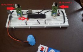
When an object moves into the room it passes through IR sensor 1 first and then IR sensor 2, this makes the microcontroller understand that something has moved into the room. In this situation it makes the LED to glow.On the other hand when the last object moves out of the room it has to pass through IR sensor 2 first and then IR sensor 1, this situation helps the microcontroller to understand that no one is present in the room now, thus it glows off the LED. In the coding part, I have used a variable “count” to count the number of objects present in the room. Count increments itself by one for every entry and decrements by one for every exit.
Interfacing L293D with 8051 Microcontroller
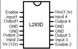
L293D is a motor driver IC. As its name suggests it can drive a motor (normally DC motors up-to certain range). Since the output voltage of 8051 is limited to 5V only thus motors with higher required voltage need some drivers to provide them their desired input voltage.What L293D does is, it takes the TTL (0/5v) input from the output pins of 8051 microcontroller and forwards the output through itself of higher voltage(required by DC motors).Connecting a DC motor directly to the pins of 8051 would not work. It may even damage the microcontroller. L293D is a 16-pin IC which can control a set of two DC motors simultaneously in any direction. It means that you can control two DC motor with a single L293D IC.

