HC-SR04 based Distance Finder gives the distance from an obstacle in centimetres. It has a range of 2cms to 400cms. The project is build around AT89S52 which is a 8051 family microcontroller. The distance is displayed on Seven Segment Displays.
Components:
AT89S52
Three 7-Seg. Disp. (Common Anode type)
HC-SR04 (Ultrasonic sensor module)
Connectors, PCBs etc.
The code is written in Assembly and is easily understandable. The project can be used in obstacle avoidance robots, etc.
Working:
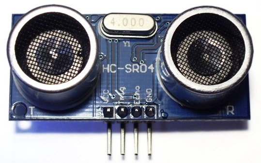
The working of the ultrasonic sensors is quite simple and they are easy to interface with the microcontroller. The sensor module has 4-pins out of which Pin-1 and Pin-4 are +Vcc and Gnd respectively.Pin-2 is Trigger and Pin-3 is Echo pin.The working of sensors can be described from the below figure :
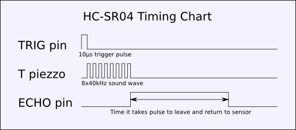
When a High pulse of 10us is applied at TRIG pin, the ultrasonic transmitter sends 8 consecutive pulses of 40kHz frequency. As the Eighth pulse is sent the ECHO pin of the sensor becomes HIGH. Now when the ultrasonic waves reflect from any surface and are received by the Receiver, the ECHO pin becomes LOW. The time it takes to leave and return to sensor is used to find the distance from the reflecting surface.
Distance in centimetres = (Time/58) cms
In Inches = (Time/148)
Distance can also be calculated by taking into account the speed of Sound (=340m/s)
Explanation of the CODE:
· The Data lines of for Seven Segment Displays are interfaced at Port-0
· Port-1’s, Pin-0,1 and 2 are select line for the SSDs
· P3.0 is connected to Trig
· P3.1 is connected to Echo pin of the sensor module
· In the main part of Program, firstly Timer-1 is initialized in mode2 (8-bit auto reload)
When P3.0 is set high, subroutine DELAY1 is called. After 10us P3.0 is reset to 0
· Now P3.1 is checked for a high signal. As P3.1 becomes high, Timer 1 starts and every time it overflows Register A is incremented.
· The Count Value loaded is to be 58 (mentioned on the datasheet). So that after 58 cycles A gets incremented once. But since the delay caused due to instructions have to compensated, the count value I used is 45 (=> 255D-210D).
· The value stored in A is used to extract the Distance measured. This is done by Division instruction.
· The 8-bit data value is sequentially sent to respective 7-Segment Display being selected through the selection lines.
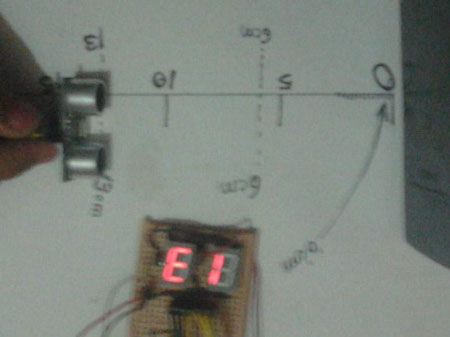
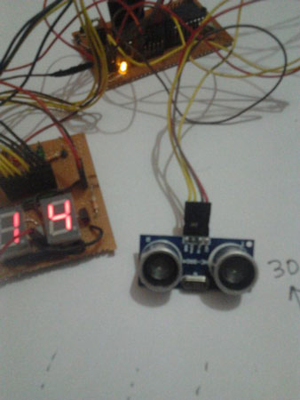
You may also like:
Project Source Code
###
ORG 00HMOV DPTR,#SSDisplay // moves the address of LUT to DPTRMOV P1,#00000000B // sets P1 as output portMOV P0,#00000000B // sets P0 as output portCLR P3.0 // sets P3.0 as output for sending triggerSETB P3.1 // sets P3.1 as input for receiving echoMOV TMOD,#00100000B // sets timer1 as mode 2 auto reload timerMAIN: MOV TL1,#210D // loads the initial value to start counting fromMOV TH1,#210D // loads the reload valueMOV A,#00000000B // clears accumulatorSETB P3.0 // starts the trigger pulseACALL DELAY1 // gives 10uS width for the trigger pulseCLR P3.0 // ends the trigger pulseHERE: JNB P3.1,HERE // loops here until echo is receivedBACK: SETB TR1 // starts the timer1HERE1: JNB TF1,HERE1 // loops here until timer overflows (ie;48 count)CLR TR1 // stops the timerCLR TF1 // clears timer flag 1INC A // increments A for every timer1 overflowJB P3.1,BACK // jumps to BACK if echo is still availableMOV R4,A // saves the value of A to R4ACALL DLOOP // calls the display loopSJMP MAIN // jumps to MAIN loopDELAY1: MOV R6,#2D // 10uS delayLOOP1: DJNZ R6,LOOP1RETDLOOP: MOV R5,#50D // loads R5 with 100DBACK1: MOV A,R4 // loads the value in R4 to AMOV B,#100D // loads B with 100DDIV AB // isolates the first digitSETB P1.0 // activates LED display unit D1ACALL DISPLAY // calls DISPLAY subroutineMOV P0,A // moves digit drive pattern for 1st digit to P0ACALL DELAY // 1mS delayACALL DELAYMOV A,B // moves the remainder of 1st division to AMOV B,#10D // loads B with 10DDIV AB // isolates the second digitCLR P1.0 // deactivates LED display unit D1SETB P1.1 // activates LED display unit D2ACALL DISPLAYMOV P0,A // moves digit drive pattern for 2nd digit to P0ACALL DELAYACALL DELAYMOV A,B // moves the remainder of 2nd division to ACLR P1.1 // deactivates LED display unit D2SETB P1.2 // activates LED display unit D3ACALL DISPLAYMOV P0,A // moves the digit drive pattern for 3rd digit to P0ACALL DELAYACALL DELAYCLR P1.2 // deactivates LED display unit D3DJNZ R5,BACK1 // repeats the display loop 100 timesRETDELAY: MOV R7,#250D // 1mS delayLABEL2: DJNZ R7,LABEL2RETDISPLAY: MOVC A,@A+DPTR // gets the digit drive pattern for the content in ARETSSDisplay: DB 0C0H // Hex code to display DISPLAY 0DB 0F9H // DISPLAY 1DB 0A2H // DISPLAY 2Project Video
Filed Under: 8051, Electronic Projects, Tech Articles







Questions related to this article?
👉Ask and discuss on EDAboard.com and Electro-Tech-Online.com forums.
Tell Us What You Think!!
You must be logged in to post a comment.