This entire project is divided in to 2 parts, the first part demonstrates the software implementation of the digital clock on Atmega16 and the second part demonstrates the hardware implementation of digital clock on WSN-EK development kit (ATMEGA324PA). In this project we have implemented a digital clock with the help of 16 bit timer. Thus this project illustrates the basic use of timer and its interrupts. The timer will interrupt Microcontroller after every 1s and perform the given ISR (Interrupt Service Routine).
Understanding Decade Counter CD4017
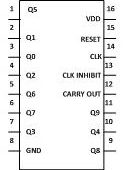
CD4017 is a 16 pin CMOS decade counter/ Divider. It takes clock signal from the clock input and turns on the 10 output in sequence, each time when it receives [[wysiwyg_imageupload::]]clock input pulses. A popular IC, CD4017 is extremely useful in various projects like Light Chaser, Matrix Die. It is also useful in many applications like Binary counter/decoder, frequency division, divide by N counting, Alarm system etc. In order to understand the working of IC CD4017, one must know about its individual pins. It has 3 input pin and 10 output pin and one is ground pin and another is used for power supply and one is Carry out pin.
Frequency and RPM Counter
Measuring frequency is one of the prime requirements for many applications. The most obvious method of measuring frequency is using CRO (or now a days using DSO). But this instrument is not handheld or available with all the students or hobbyists at any time. It is actually laboratory instrument and not the portable one. Also…
Clap counter using 8051 microcontroller (AT89C51)
This article explains the concept behind interfacing a sound sensor with the 8051 microcontroller (AT89C51). This project increases the count by one every time a sound is produced. It works well with the sound of a clap. The number of claps is displayed on an LCD module. The circuit consists of four modules, namely, a sound sensor, an amplifying circuit, a control circuit and a display module. The code for interfacing the sound sensor with the MCU is written in C language.The connections of different modules are shown in the circuit diagram. The data pins of the LCD are connected to port P2, while the control pins (RS, R/W & EN) are connected to pins 1-3 of port P1of AT89C51, respectively. The microcontroller receives sound pulses through the first pin of port P0.A condenser microphone is used to sense the sound produced by the clap. This mic is connected to a two stage transistor amplifier.
Automatic bidirectional visitor counter using 8051 microcontroller (AT89C51)
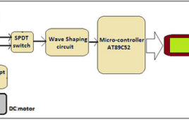
A counter that can change its state in either direction, under control of an up–down selector input, is known as an up–down counter. The circuit given here can [[wysiwyg_imageupload::]]count numbers from 0 to 9999 in up and down modes depending upon the state of the selector. It can be used to count the number of persons entering a hall in the up mode at entrance gate. In the down mode, it can count the number of persons leaving the hall by decrementing the count at exit gate. It can also be used at gates of parking areas and other public places.This circuit divided in three parts: sensor, controller and counter display. The sensor would observe an interruption and provide an input to the controller which would run the counter in up/down mode depending upon the selector setting. The same count is displayed on a set of 7-segment displays through the controller. Read more to find out about working of the circuit and how microcontroller is coded.
Up down counter using 8051 microcontroller (AT89C51)
This article shows an easy to build up down counter. The counter is based around the 8051 microcontroller (AT89C51). Two switches are provided, one for [[wysiwyg_imageupload::]]increment and second for decrement. The switches can also be replaced by sensors to increment or decrement. In this circuit, four seven segment display are used to show the value of count. The maximum value of count is 9999. The circuit uses the concept of multiplexing of seven segment to display the value of count. For more details on seven segment multiplexing, refer article titled “Seven segment multiplexing”.In this circuit data output for the seven segment is given on the port P2 of the microcontroller AT89C51. The control signals for enabling the seven segment displays are given on pin no. 1,2,3,4 of microcontroller. The input of switches is taken on pin number P3.5 and P3.6. Switch connected on pin P3.5 is the increment switch and that at pin P3.6 is the decrement switch. The seven segment used here are common anode.


