This is a very interesting and funny project made with the help of the GR SAKURA board which can record the speech and play it back in the voice of a parrot. It might look like a toy but there are lot of technology behind its working like voice sampling, memory card interfacing, PWM etc.
Voice signals are continuous analog signals and the digital devices like microcontrollers cannot handle the continuous analog signals. Most of the microcontrollers have an ADC module which can do analog to digital conversion. The microcontroller uses sampling technique to convert the continuous analog signals to discrete digital equivalent samples. While recording the voice, the GR SAKURA board samples the voice signals and writes the sampled values to a file at the sampling time itself.
The same file is opened again and reads the values at double the frequency at which they are sampled.This creates a sensation of a parrot talk even though the sampled read from the file corresponds to a human voice. The digital microcontrollers based devices cannot produce analog output also, since their output will be always either logic high or logic low. To generate the effect of the continuous analog voice signal, the GR SAKURA uses PWM (Pulse Width Modulation) technique.
DESCRIPTION
The GR SAKURA reads the digital equivalent value of the sampled analog signal and writes the same value to the micro SD card at the same sampling time itself. While playing back, the GR SAKURA reads the same sampled values from the micro SD card to generate the PWM equivalent of the analog voice signals at an output pin where the loudspeaker is connected.
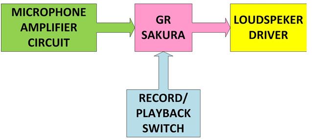
The GR SAKURA board has a micro SD card slot and the board is connected to a microphone amplifier circuit at its input and loudspeaker driver circuit at its output. The project uses a simple condenser microphone which captures the voice input and the fetch them to one of the ADC channels of the GR SAKURA. The entire system can be divided into the following blocks:

Fig. 1: Block Diagram of GR Sakura based Talking Parrot
1) MICROPHONE AMPLIFIER CIRCUIT
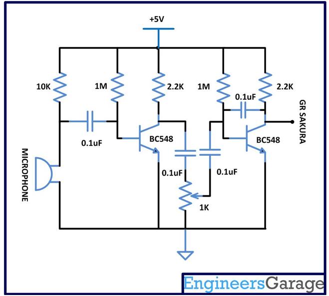
The microphone used here is a small commonly found condenser microphone. The microphone captures the voice signals from the surrounding and produces the voltage equivalent of the sound signals. The amplitude of the sound signal output from the microphone is very feeble and they need to be amplified several times before they are applied to the microcontroller or any other devices. This circuit blocks uses two stage transistor based amplifier which are designed amplify the analog voice signals to the required amplitude level for the GR SAKURA.

Fig. 2: Circuit Diagram of Microphone Amplifier
The supply voltage is taken from the GR SAKURA board itself operating with USB power. To get the +5V from the 5 volt VCC pin of the SAKURA board, the jumper J2 is shorted.
2) GR SAKURA
For the recording of voice signals the TIMER 0 of the GR SAKURA is used to generate exact time intervals of 100 us at which the voice signals needs to be sampled. The 100 us sampling period means 10 KHz of sampling frequency which is good enough for sampling the human voice falling at a range of 3 to 4 KHz. At the same time interval the same voice sampled value is written to the micro SD card using memory card interfacing library. A file of predefined name is created and opened in writing mode into which the sampled values are written at each and every sampling period. Once the recording is completed the file is closed.
The voltage at the ADC channel or the analog input of the GR SAKURA will be the sum of quiescent voltage of the transistor amplifier + amplified voice signals. The quiescent voltage is subtracted from the total voltage to get the voice signal. For playing back the voice, the same file is opened in the reading mode and the sample values are read back from the file.
The sound signals are played back at double the frequency at which they are sampled. This makes the speech play at double the speed and creates a sensation of parrot voice. Thissample values are used to modify the ON period and the OFF period of the timer in such a way that the entire sampling period is always constant. This generates a PWM equivalent of the input voice signal at that digital output pin, but at double the frequency than the original speech signals. When this PWM wave is applied to the loudspeaker it will produce the same sound which has been captured through the microphone.
The code written for this uses the functions like digitalWrite()and analogRead()to write digital values to a digital output pin and read the analog input values from an analog input pin respectively. The files “intvect.c” of the Cloud Compiler IDE is modified to enable the TIMER0 interrupt. For writing into and reading back from the micro SD card the GR SAKURA uses the functions like begin(), open(), write(), read(), close() and remove() from the SD card interfacing library.
The sampling frequency is varied by changing the value of the TMR1.TCCR.BYTE. The value for the byte “0b01000” corresponds to a clock division of 2 for the TIMER 0’s input clock and the value “0b01001” corresponds to a clock division of 4 for the TIMER 0’s input clock.
Loudspeaker Driver and Playback
3) LOUDSPEAKER DRIVER
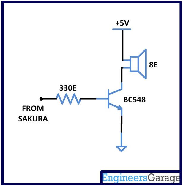
The Loudspeaker used to reproduce the sound signals in this project is an 8 ohm loudspeaker. The 8 ohm loudspeaker consumes lot of current while it operates but the current sourcing capabilities of the digital output pin of the microcontrollers are limited. Here the output pin is connected to the base of a transistor and the Loudspeaker is connected to the collector of a transistor. Very low base current is required to drive the loudspeaker at the collector of the transistor with the required amount of current.

Fig. 3: Circuit Diagram of Loud Speaker Driver
4) RECORD/PLAYBACK SWITCH
The record and playback switch is a simple push button which is pulled down using a 1K ohm resistor and when pressed it makes contact with the VCC. The button is connected to the pin number 8 of the GR SAKURA which is configured as an input pin. Before recording, the code will wait till the value at the pin number 8 becomes logic high which will happens when someone presses the button. The digital value is read from this pin using the functiondigitalRead().

Fig. 4: Circuit Diagram of GR Sakura based Talking Parrot

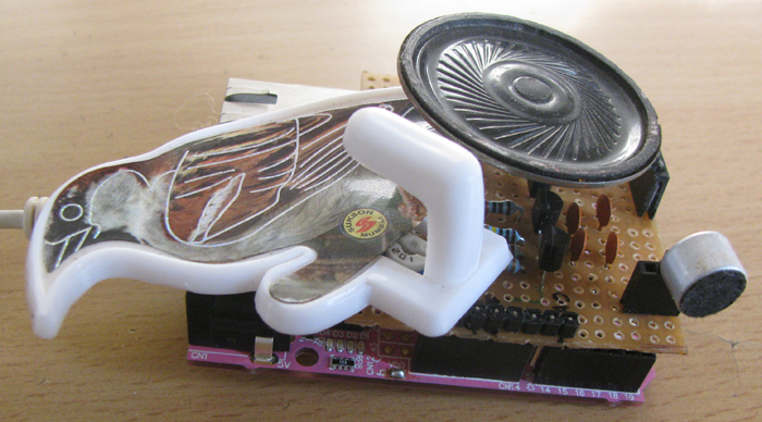
Fig. 5: Prototype of GR Sakura based Talking Parrot
Project Datasheet
Project Video
Filed Under: Electronic Projects
Filed Under: Electronic Projects


Questions related to this article?
👉Ask and discuss on EDAboard.com and Electro-Tech-Online.com forums.
Tell Us What You Think!!
You must be logged in to post a comment.