Engineers Garage

  • Electronic Projects & Tutorials
    • Electronic Projects
      • Arduino Projects
      • AVR
      • Raspberry pi
      • ESP8266
      • BeagleBone
      • 8051 Microcontroller
      • ARM
      • PIC Microcontroller
      • STM32
    • Tutorials
      • Audio Electronics
      • Battery Management
      • Brainwave
      • Electric Vehicles
      • EMI/EMC/RFI
      • Hardware Filters
      • IoT tutorials
      • Power Tutorials
      • Python
      • Sensors
      • USB
      • VHDL
    • Circuit Design
    • Project Videos
    • Components
  • Articles
    • Tech Articles
    • Insight
    • Invention Stories
    • How to
    • What Is
  • News
    • Electronic Product News
    • Business News
    • Company/Start-up News
    • DIY Reviews
    • Guest Post
  • Forums
    • EDABoard.com
    • Electro-Tech-Online
    • EG Forum Archive
  • DigiKey Store
    • Cables, Wires
    • Connectors, Interconnect
    • Discrete
    • Electromechanical
    • Embedded Computers
    • Enclosures, Hardware, Office
    • Integrated Circuits (ICs)
    • Isolators
    • LED/Optoelectronics
    • Passive
    • Power, Circuit Protection
    • Programmers
    • RF, Wireless
    • Semiconductors
    • Sensors, Transducers
    • Test Products
    • Tools
  • Learn
    • eBooks/Tech Tips
    • Design Guides
    • Learning Center
    • Tech Toolboxes
    • Webinars & Digital Events
  • Resources
    • Digital Issues
    • EE Training Days
    • LEAP Awards
    • Podcasts
    • Webinars / Digital Events
    • White Papers
    • Engineering Diversity & Inclusion
    • DesignFast
  • Guest Post Guidelines
  • Advertise
  • Subscribe

Timer Circuit using IC CD 4060

By Ashutosh Bhatt November 15, 2012

Several times we forget to switch off the gas, electric oven, stove or motor while watching TV or taking on the phone or while talking to a friend in your neighborhood. To solve this problem we have described a circuit below which gives an alarm after the preset time interval selected by you. In this you can select 7 different time intervals with the help of a rotary switch. Therefore after a preset interval of time it will give a loud alarm and reminds you that you have to off your machine or gas.
 
The timer circuit is built around the CD4060 which is 14 stage ripple carry binary counter, divider and an oscillator. Its built in oscillator is main feature of this IC that’s why it can be used in numerous application like flasher, clock generator in timer circuits.  Image below shows the pin layout of the IC:
[[wysiwyg_imageupload:7508:]]
Fig. 1: Pin Diagram Of CD 4060 IC

Here, IC1 works as frequency divider circuit. Its inbuilt oscillator is based on three inverters. The basic frequency of the internal oscillator is determined by the value of the capacitor connected to its pin 9 and the resistor connected to pin 10. By increasing or decreasing the value of capacitor and resistor, we can change the time delay for the period of on and off. Internally the oscillator signal is applied to the first bistable which drives the second bistable and so on. Since each bistable divides its input signal by two, a total of fifteen signals are available, each of half the frequency of the previous one.Output Qn is the nth stage of the counter, representing 2n, for example Q4 is 24 = 16 (1/16 of clock frequency) and Q14 is 214 = 16384 (1/16384 of clock frequency). Note that Q1-3 and Q11 are not available
 
Alarm can be adjusted for duration of 30 seconds to 2 hour 30 minutes. Here we have used a rotary switch to select the time required. When power is ON, the pulse at the junction R1 and C2 resets the counter and counting starts. When counter reaches bit 128(Q4), pin 7 goes high so that the buzzer (connected with the relay) with the transistor turn on. Similarly if you have connected the rotary switch to pin 5, then at this time Q5 gives 32 divisions and it will give an alarm after 30 seconds and continue to give alarm until you switch off the alarm externally. This happens because we have connected pin 11 through a diode, oscillation stop and IC remains latched in high state until it resets. If you want to get alarm after every preset time interval, then remove this diode. Now we can connect other output also with the rotary switch to get different time period.
 
When S1 selected the timer have the time as the following table-
 
  S1 connected to pin 
Time
7
30 seconds
5
1 minutes10seconds
4
2 minutes20seconds
6
4 minutes30seconds
14
10 minutes
13
20 minutes
15
40 minutes
1
2 hour 30 minutes
 

It is important to connect pin 12 (reset pin) to ground for enabling the IC to oscillate and we have connected it to positive supply. This is done so that it instantly stops the IC from oscillating and resets it back to its original stage. It, thus makes sure that we will get equal time period of On/Off time. For example suppose initially the pin is connected to the ground for enabling the IC to oscillate let say for 5 minute, connecting the pin to the positive would immediately halt the counting after 5 minutes and reset it back to zero. So that counter will start again. 
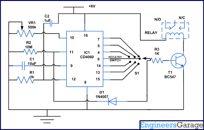
Circuit Diagrams

Circuit-Diagram-Timer-Circuit-using-IC-CD-4060

Project Components

  • Capacitor
  • Relay Switch
  • Resistor
  • Speaker
  • Transistor BC547


Filed Under: Electronic Projects
Tagged With: cd 4060, ic, timer, timer circuit
 

Next Article

← Previous Article
Next Article →

Questions related to this article?
👉Ask and discuss on Electro-Tech-Online.com and EDAboard.com forums.


Tell Us What You Think!! Cancel reply

You must be logged in to post a comment.

EE TECH TOOLBOX

“ee
Tech Toolbox: 5G Technology
This Tech Toolbox covers the basics of 5G technology plus a story about how engineers designed and built a prototype DSL router mostly from old cellphone parts. Download this first 5G/wired/wireless communications Tech Toolbox to learn more!

EE Learning Center

EE Learning Center
“engineers
EXPAND YOUR KNOWLEDGE AND STAY CONNECTED
Get the latest info on technologies, tools and strategies for EE professionals.

HAVE A QUESTION?

Have a technical question about an article or other engineering questions? Check out our engineering forums EDABoard.com and Electro-Tech-Online.com where you can get those questions asked and answered by your peers!


RSS EDABOARD.com Discussions

  • Right Half Plane Zero
  • Single ended measuring ports and balanced antenna
  • Thermal modelling of repetitive power pulse
  • Testing 5kW Grid Tied inverter over 200-253VAC
  • Resistor Selection for Amplifier Layout

RSS Electro-Tech-Online.com Discussions

  • Fun with AI and swordfish basic
  • Simple LED Analog Clock Idea
  • Is AI making embedded software developers more productive?
  • Can I make two inputs from one??
  • Behlke swich

Featured – LoRa/LoRaWan Series

  • What is the LoRaWAN network and how does it work?
  • Understanding LoRa architecture: nodes, gateways, and servers
  • Revolutionizing RF: LoRa applications and advantages
  • How to build a LoRa gateway using Raspberry Pi
  • How LoRa enables long-range communication
  • How communication works between two LoRa end-node devices

Recent Articles

  • RPi Python Programming 21: The SIM900A AT commands
  • RPi Python Programming 22: Calls & SMS using a SIM900A GSM-GPRS modem
  • RPi Python Programming 23: Interfacing a NEO-6MV2 GPS module with Raspberry Pi
  • RPi Python Programming 24: I2C explained
  • RPi Python Programming 25 – Synchronous serial communication in Raspberry Pi using I2C protocol

EE ENGINEERING TRAINING DAYS

engineering

Submit a Guest Post

submit a guest post
Engineers Garage
  • Analog IC TIps
  • Connector Tips
  • Battery Power Tips
  • DesignFast
  • EDABoard Forums
  • EE World Online
  • Electro-Tech-Online Forums
  • EV Engineering
  • Microcontroller Tips
  • Power Electronic Tips
  • Sensor Tips
  • Test and Measurement Tips
  • 5G Technology World
  • Subscribe to our newsletter
  • About Us
  • Contact Us
  • Advertise

Copyright © 2025 WTWH Media LLC. All Rights Reserved. The material on this site may not be reproduced, distributed, transmitted, cached or otherwise used, except with the prior written permission of WTWH Media
Privacy Policy

Search Engineers Garage

  • Electronic Projects & Tutorials
    • Electronic Projects
      • Arduino Projects
      • AVR
      • Raspberry pi
      • ESP8266
      • BeagleBone
      • 8051 Microcontroller
      • ARM
      • PIC Microcontroller
      • STM32
    • Tutorials
      • Audio Electronics
      • Battery Management
      • Brainwave
      • Electric Vehicles
      • EMI/EMC/RFI
      • Hardware Filters
      • IoT tutorials
      • Power Tutorials
      • Python
      • Sensors
      • USB
      • VHDL
    • Circuit Design
    • Project Videos
    • Components
  • Articles
    • Tech Articles
    • Insight
    • Invention Stories
    • How to
    • What Is
  • News
    • Electronic Product News
    • Business News
    • Company/Start-up News
    • DIY Reviews
    • Guest Post
  • Forums
    • EDABoard.com
    • Electro-Tech-Online
    • EG Forum Archive
  • DigiKey Store
    • Cables, Wires
    • Connectors, Interconnect
    • Discrete
    • Electromechanical
    • Embedded Computers
    • Enclosures, Hardware, Office
    • Integrated Circuits (ICs)
    • Isolators
    • LED/Optoelectronics
    • Passive
    • Power, Circuit Protection
    • Programmers
    • RF, Wireless
    • Semiconductors
    • Sensors, Transducers
    • Test Products
    • Tools
  • Learn
    • eBooks/Tech Tips
    • Design Guides
    • Learning Center
    • Tech Toolboxes
    • Webinars & Digital Events
  • Resources
    • Digital Issues
    • EE Training Days
    • LEAP Awards
    • Podcasts
    • Webinars / Digital Events
    • White Papers
    • Engineering Diversity & Inclusion
    • DesignFast
  • Guest Post Guidelines
  • Advertise
  • Subscribe