Engineers Garage

  • Electronic Projects & Tutorials
    • Electronic Projects
      • Arduino Projects
      • AVR
      • Raspberry pi
      • ESP8266
      • BeagleBone
      • 8051 Microcontroller
      • ARM
      • PIC Microcontroller
      • STM32
    • Tutorials
      • Audio Electronics
      • Battery Management
      • Brainwave
      • Electric Vehicles
      • EMI/EMC/RFI
      • Hardware Filters
      • IoT tutorials
      • Power Tutorials
      • Python
      • Sensors
      • USB
      • VHDL
    • Circuit Design
    • Project Videos
    • Components
  • Articles
    • Tech Articles
    • Insight
    • Invention Stories
    • How to
    • What Is
  • News
    • Electronic Product News
    • Business News
    • Company/Start-up News
    • DIY Reviews
    • Guest Post
  • Forums
    • EDABoard.com
    • Electro-Tech-Online
    • EG Forum Archive
  • DigiKey Store
    • Cables, Wires
    • Connectors, Interconnect
    • Discrete
    • Electromechanical
    • Embedded Computers
    • Enclosures, Hardware, Office
    • Integrated Circuits (ICs)
    • Isolators
    • LED/Optoelectronics
    • Passive
    • Power, Circuit Protection
    • Programmers
    • RF, Wireless
    • Semiconductors
    • Sensors, Transducers
    • Test Products
    • Tools
  • Learn
    • eBooks/Tech Tips
    • Design Guides
    • Learning Center
    • Tech Toolboxes
    • Webinars & Digital Events
  • Resources
    • Digital Issues
    • EE Training Days
    • LEAP Awards
    • Podcasts
    • Webinars / Digital Events
    • White Papers
    • Engineering Diversity & Inclusion
    • DesignFast
  • Guest Post Guidelines
  • Advertise
  • Subscribe

Variable Power Supply with LCD

By Ganesh Selvaraj July 2, 2014

Are you an electronic hobbyist? Then an adjustable power supply is a must for your various needs. This project explains how to make a LM317 based adjustable power supply unit with a digital display. For this project reader should have knowledge of how to start with AVR and interface LCD with AVR.

Components Required

1. LM317 IC
 
2. Resistor – 240 Ohms
 
3.  Capacitors – 0.1uF, 10uF
 
4.  Potentiometer – 5k
 
5. 30V/1A Adapter (or a transformer + Bridge wave rectifier IC)
 
6. ATMega16 Developments Board
 
7. 16 x 2 LCD  Display

7. 16 x 2 LCD Board


Circuit Design

Well the power supply circuit is very simple and can be found in the datasheet of LM317 itself.

Circuit Diagram of LM317 IC based Variable Power Supply

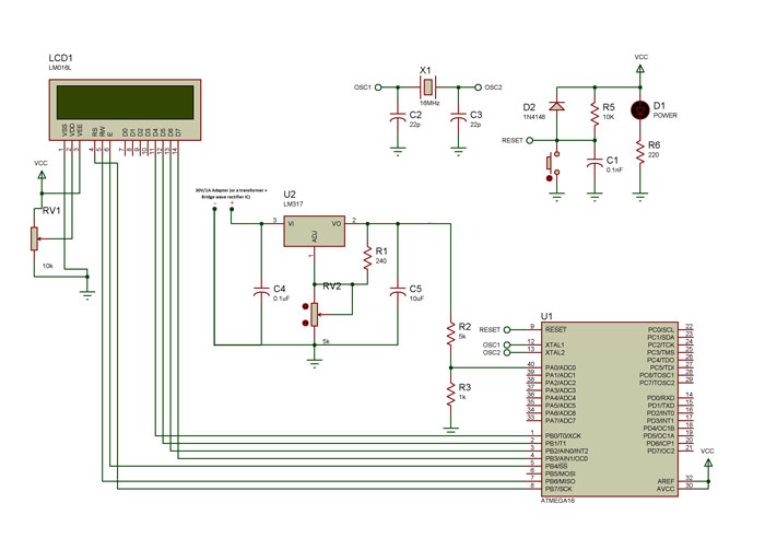
Fig. 1: Circuit Diagram of LM317 IC based Variable Power Supply

The output voltage is given by the equation,
 
Vout = 1.25 (1+ R2/R1) + Iadj x R2
 
What we need to design is the additional voltmeter kind of arrangements using a microcontroller in order to display the output voltage value accurately. For this, we use the ADC feature of the microcontroller.

 
But the problem is that ATmega16 can only take up to 5V. Input voltage more than that can fry up the controller.
 
Solution: A Voltage divider circuit!
 

Circuit Diagram of Voltage Divider Circuit for power output

Fig. 2: Circuit Diagram of Voltage Divider Circuit for power output

Here R1 and R2 are the resistors and Vin is the input voltage. The output voltage Vout is given as:

Vout =  Vin X R2/(R1 + R2) .  .  .  .  .  .  .  .  .  .  .  .  .  .  . (1)

We choose the resistor values based on our requirements. Like, say now our maximum voltage to be measured is 30V but we can only give up to 5V to our controller.

So here maximum Vin = 30V and maximum Vout = 5V

Substituting in equation (1) and on solving, we get

R1:R2 = 5 : 1

So we can take R1= 5kOhm and R2=1k Ohm

Code Explanation

– Initialize the 16 bit ADC mode of the controller.
 
– Initialize the LCD function.
 
– Enter an infinite loop.
 
– Read the voltage level at ADC1, convert it into a 16-bit discreet value (0 to 1023) and store it in a variable “val”.
 
– Divide the value at “val” by 1024 and then multiply it with 30. This gives you the original applied voltage value.
 
– Now display this value in the LCD.


Conversion Process Example

• Let us say that we applied some input voltage Vin= 24V to the system
 
• Now from the design equation, the output voltage of voltage divider circuit can be calculated. Here the output would be 4V, which is the input to the ADC pin of microcontroller.
 
• The controller would covert the analog value (0-5V) into a discreet value of range, 0-1023. In this case the value would be around 819.
 
• Next, this discreet value is again converted into the original input voltage range which is 0-30V through programming. Here the value obtained would be 23.99, which is almost equal to 24V!

Block Diagram of AVR ATMega16 based Variable Power Supply

Fig. 3: Block Diagram of AVR ATMega16 based Variable Power Supply


How we display decimals:

Let us say we got a value val = 24.93
 
Now “lcd_write_int()” function only accepts whole numbers and no decimal part.
 
So what we do is,

Step 1: Multiply ‘val’ with 100

Val x 100 = 24.93 x 100 = 2493 (say we name it ‘a’)
 
Step 2: Obtain integer part by using ‘/ ’operator

I = a / 100 = 2493 / 100 = 24 (Integer)

 
Step 3: Obtain decimal part as another integer using ‘%’ operator

D = a % 100 = 2493 % 100 = 93

Step 4:

First display the integer part followed by ‘.’ and then the decimal part.

Example: display(I+’.’+D)   à I.D

Representational image of display panel for AVR ATMega16 based Adjustable Power Supply

Fig. 4: Representational image of display panel for AVR ATMega16 based Adjustable Power Supply

Project Source Code

###


LCD.H


#ifndef LCD_H_
#define LCD_H_
#define rs PA7
#define rw PA6
#define en PA4
void lcd_init();
void dis_cmd(char);
void dis_data(char);
void lcdcmd(char);
void lcddata(char);
void clrscr();
void gotoxy(char,char);
void LCD_write_string(const char *);
void lcd_write_int(int,unsigned int);
#endif


Variable.C


/*
 * VARIABLE.c
 *
 * Created: 5/29/2014 3:53:39 PM
 *  Author: GANESH SELVARAJ
 */ 
#define F_CPU 16000000UL
#include <avr/io.h>
#include <util/delay.h>
#include "lcd.h"
void SetADC()
{
ADMUX|=(1<<REFS0);
ADCSRA=(1<<ADEN)|(7<<ADPS0);
}
uint16_t ReadADC(uint8_t ch)
{
//Select ADC Channel ch must be 0-7
ch=ch&0b00000111;
ADMUX&=0b11100000;
ADMUX|=ch;
//Start Single conversion
ADCSRA|=(1<<ADSC);
//Wait for conversion to complete
while(!(ADCSRA & (1<<ADIF)));
//Clear ADIF by writing one to it
ADCSRA|=(1<<ADIF);
return(ADC);
}
void Waiting(int j) // simple delay function
{
uint8_t i;
for(i=0;i<j;i++)
_delay_ms(200);
}
int main(void)
{
int v;
_delay_ms(50); // delay of 50 milliseconds
SetADC();
lcd_init();
LCD_write_string("Adj Power Supply");
while(1)
    {
gotoxy(1,1);
LCD_write_string("Voltage:");
v=((ReadADC(0)/1024.00)*3000.00);
lcd_write_int((v/100),2);
dis_data('.');
lcd_write_int((v%100),2);
dis_data('V');
dis_data(' ');
Waiting(2);
    }
}


LCD.H


/*
 * EG_LCD.c
 *
 * Created: 2/9/2014 10:49:54 PM
 *  Author: stranger
 */ 
#include<avr/io.h>
#include<util/delay.h>
#include<inttypes.h>
#include "lcd.h"
void LCD_write_string(const char *str) //store address value of the string in pointer *str
{
int i=0;
while(str[i]!='') // loop will go on till the NULL character in the string
{
if (str[i]=='*')
{
i++;
int8_t cc=str[i]-'0';
if(cc>=0 && cc<=7)
{
dis_data(cc);
}
else
{
dis_data('%');
dis_data(str[i]);
}
}
else dis_data(str[i]); // sending data on LCD byte by byte
i++;
}
return;
}
void lcd_init() // function for initialize
{
DDRB=0xFF;
dis_cmd(0x02); // to initialize LCD in 4-bit mode.
dis_cmd(0x28); //to initialize LCD in 2 lines, 5X7 dots and 4bit mode.
dis_cmd(0x0C);
dis_cmd(0x06);
dis_cmd(0x0E);
gotoxy(0,0);
}
void dis_cmd(char cmd_value)
{
char cmd_value1;
cmd_value1 = ((cmd_value>>4) & 0x0F); //shift 4-bit and mask
lcdcmd(cmd_value1); // send to LCD
cmd_value1 = cmd_value & 0x0F; //mask lower nibble because PA4-PA7 pins are used.
lcdcmd(cmd_value1); // send to LCD
}
void dis_data(char data_value)
{
char data_value1;
data_value1=((data_value>>4)&0x0F);
lcddata(data_value1);
data_value1=data_value&0x0F;
lcddata(data_value1);
}
void lcdcmd(char cmdout)
{
PORTB=cmdout;
PORTB&=~(1<<rs);
PORTB&=~(1<<rw);
PORTB|=(1<<en);
_delay_ms(1);
PORTB&=~(1<<en);
}
void lcddata(char dataout)
{
PORTB=dataout;
PORTB|=(1<<rs);
PORTB&=~(1<<rw);
PORTB|=(1<<en);
_delay_ms(1);
PORTB&=~(1<<en);
}
void clrscr()
{
_delay_ms(10);
dis_cmd(0x01);
_delay_ms(100);
}
void gotoxy(char a,char b)
{
if(a==0)  a=0b10000000;
else if(a==1) a=0b11000000;
else if(a==2) a=0b10010100;
else if(a==3) a=0b11010100;
dis_cmd(a+b); 
}
void lcd_write_int(int val,unsigned int field_length)
{
char str[5]={0,0,0,0,0};
uint8_t i=4,j=0;
while(val)
{
str[i]=val%10;
val=val/10;
i--;
}
if(field_length==-1)
while(str[j]==0) j++;
else
j=5-field_length;
if(val<0) dis_data('-');
for(i=j;i<5;i++)
{
dis_data(48+str[i]);
}
}
###


Circuit Diagrams

Circuit-Diagram-Avr-Atmega16-Based-Adjustable-Power-Supply


Filed Under: Electronic Projects
Tagged With: avr, lcd, power supply
 

Next Article

← Previous Article
Next Article →

Questions related to this article?
👉Ask and discuss on Electro-Tech-Online.com and EDAboard.com forums.


Tell Us What You Think!! Cancel reply

You must be logged in to post a comment.

EE TECH TOOLBOX

“ee
Tech Toolbox: Internet of Things
Explore practical strategies for minimizing attack surfaces, managing memory efficiently, and securing firmware. Download now to ensure your IoT implementations remain secure, efficient, and future-ready.

EE Learning Center

EE Learning Center
“engineers
EXPAND YOUR KNOWLEDGE AND STAY CONNECTED
Get the latest info on technologies, tools and strategies for EE professionals.

HAVE A QUESTION?

Have a technical question about an article or other engineering questions? Check out our engineering forums EDABoard.com and Electro-Tech-Online.com where you can get those questions asked and answered by your peers!


RSS EDABOARD.com Discussions

  • Multiple DC/DC converters and a single input source
  • MOSFET thermal noise in Weak vs Strong inversion
  • High Side current sensing
  • Xiaomi Mijia 1C Robot problem of going backwards while working
  • Will this TL084C based current clamp circuit work?

RSS Electro-Tech-Online.com Discussions

  • Curved lines in PCB design
  • using a RTC in SF basic
  • Parts required for a personal project
  • Wideband matching an electrically short bowtie antenna; 50 ohm, 434 MHz
  • PIC KIT 3 not able to program dsPIC

Featured – RPi Python Programming (27 Part)

  • RPi Python Programming 21: The SIM900A AT commands
  • RPi Python Programming 22: Calls & SMS using a SIM900A GSM-GPRS modem
  • RPi Python Programming 23: Interfacing a NEO-6MV2 GPS module with Raspberry Pi
  • RPi Python Programming 24: I2C explained
  • RPi Python Programming 25 – Synchronous serial communication in Raspberry Pi using I2C protocol
  • RPi Python Programming 26 – Interfacing ADXL345 accelerometer sensor with Raspberry Pi

Recent Articles

  • AC-DC power supply extends voltage range to 800 V DC
  • Infineon’s inductive sensor integrates coil system driver, signal conditioning circuits and DSP
  • Arm Cortex-M23 MCU delivers 87.5 µA/MHz active mode
  • STMicroelectronics releases automotive amplifiers with in-play open-load detection
  • Convection-cooled power controller integrates EtherCat connectivity

EE ENGINEERING TRAINING DAYS

engineering

Submit a Guest Post

submit a guest post
Engineers Garage
  • Analog IC TIps
  • Connector Tips
  • Battery Power Tips
  • DesignFast
  • EDABoard Forums
  • EE World Online
  • Electro-Tech-Online Forums
  • EV Engineering
  • Microcontroller Tips
  • Power Electronic Tips
  • Sensor Tips
  • Test and Measurement Tips
  • 5G Technology World
  • Subscribe to our newsletter
  • About Us
  • Contact Us
  • Advertise

Copyright © 2025 WTWH Media LLC. All Rights Reserved. The material on this site may not be reproduced, distributed, transmitted, cached or otherwise used, except with the prior written permission of WTWH Media
Privacy Policy

Search Engineers Garage

  • Electronic Projects & Tutorials
    • Electronic Projects
      • Arduino Projects
      • AVR
      • Raspberry pi
      • ESP8266
      • BeagleBone
      • 8051 Microcontroller
      • ARM
      • PIC Microcontroller
      • STM32
    • Tutorials
      • Audio Electronics
      • Battery Management
      • Brainwave
      • Electric Vehicles
      • EMI/EMC/RFI
      • Hardware Filters
      • IoT tutorials
      • Power Tutorials
      • Python
      • Sensors
      • USB
      • VHDL
    • Circuit Design
    • Project Videos
    • Components
  • Articles
    • Tech Articles
    • Insight
    • Invention Stories
    • How to
    • What Is
  • News
    • Electronic Product News
    • Business News
    • Company/Start-up News
    • DIY Reviews
    • Guest Post
  • Forums
    • EDABoard.com
    • Electro-Tech-Online
    • EG Forum Archive
  • DigiKey Store
    • Cables, Wires
    • Connectors, Interconnect
    • Discrete
    • Electromechanical
    • Embedded Computers
    • Enclosures, Hardware, Office
    • Integrated Circuits (ICs)
    • Isolators
    • LED/Optoelectronics
    • Passive
    • Power, Circuit Protection
    • Programmers
    • RF, Wireless
    • Semiconductors
    • Sensors, Transducers
    • Test Products
    • Tools
  • Learn
    • eBooks/Tech Tips
    • Design Guides
    • Learning Center
    • Tech Toolboxes
    • Webinars & Digital Events
  • Resources
    • Digital Issues
    • EE Training Days
    • LEAP Awards
    • Podcasts
    • Webinars / Digital Events
    • White Papers
    • Engineering Diversity & Inclusion
    • DesignFast
  • Guest Post Guidelines
  • Advertise
  • Subscribe