Note: it’s recommended to follow this VHDL tutorial series in order, starting with the first tutorial.
In the previous tutorial, VHDL tutorial – 14, we designed two circuits using VHDL: a 1×8 de-multiplexer and a 8×1 multiplexer.
In this project, we will,
- Write a VHDL program to build a clocked SR Latch (flip-flop) circuit
- Verify the output waveform of the program (the digital circuit) with the flip-flop circuit’s truth table
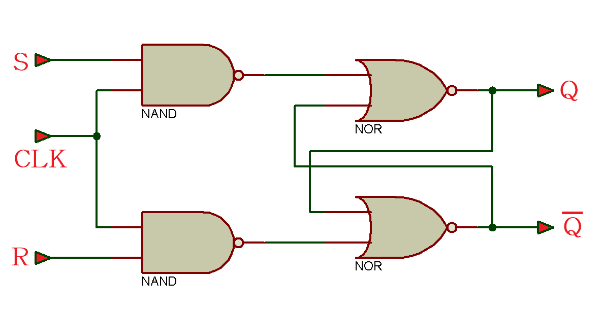
A clocked SR latch circuit:
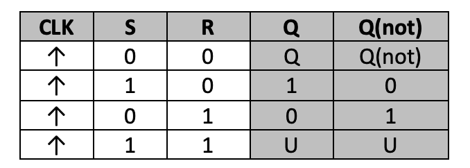
Truth table
Now, let’s write, compile, and simulate a VHDL program. Then, we’ll get the output in waveform and verify it with the given truth table.
Before starting, be sure to review the step-by-step procedure provided in VHDL Tutorial – 3 to properly design the project, as well as edit and compile the program and the waveform file, including the final output.
For this tutorial, we’ve used a behavioral modeling style to write the VHDL program that will build the flip-flop circuit. This is the preferred modeling style for sequential digital circuits.
VHDL program
library ieee;
use ieee.std_logic_1164.all;
entity RS_FF is
port (clk,r,s : in std_logic;
Q: out std_logic;
Qnot : out std_logic);
end RS_FF;
architecture RSFF_arch of RS_FF is
signal t1,t2 : std_logic;
begin
t1 <= r nor t2;
t2 <= s nor t1;
process (clk,r,s)
begin
if(clk’event and clk=’1′ ) then
if(r=’0′ and s=’0′) then
Q <=t1;
Qnot <= t2;
elsif(r=’0′ and s=’1′) then
Q <=’1′;
Qnot <=’0′;
elsif(r=’1′ and s=’0′) then
Q <=’0′;
Qnot <=’1′;
elsif(r=’1′ and s=’1′) then
Q <=’X’;
Qnot <=’X’;
end if;
end if;
end process;
end RSFF_arch;
To refresh your memory about how this works, go through the first two VHDL tutorials (1 and 2) of this series.
Next, compile the above program, creating a waveform file with all of the necessary inputs and outputs that are listed, and simulate the project. You should get the following result…
Simulation waveform
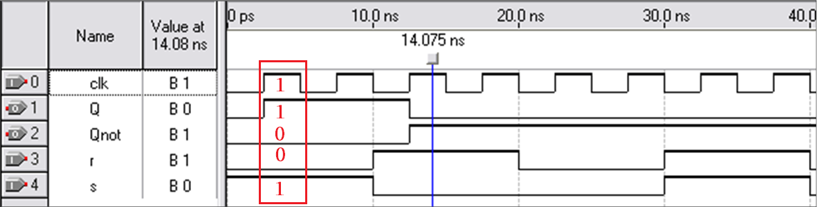
As shown in this figure, when the clock input is ‘1,’ then “s” is ‘1.’ And when “r” is ‘0,’ the flip-flop is set – which means that the Q output is ‘1’ and the Qnot is ‘0.’
Be sure to verify the different combinations with the given truth table.
In the next tutorial, we’ll design a D flip-flop by using VHDL.
Filed Under: Tutorials, VHDL, VHDL

Questions related to this article?
👉Ask and discuss on EDAboard.com and Electro-Tech-Online.com forums.
Tell Us What You Think!!
You must be logged in to post a comment.