What is VHDL?
- VHDL is a short form of VHSlC Hardware Description Language where VHSIC stands for Very High Speed Integrated Circuits
- It’s a hardware description language – means it describes the behavior of a digital circuit, and also it can be used to derive or implement a digital circuit/system hardware
- It can be used for digital circuit synthesis as well as simulation.
- It is used to build digital system/circuit using Programmable Logic Device like CPLD ( Complex Programmable Logic Device) or FPGA (Field Programmable Gate Array)
- VHDL program (code) is used to implement digital circuit inside CPLD / FPGA, or it can be used to fabricate ASIC (Application Specific Integrated Circuit)
- It is very useful in developing high end, sophisticated microprocessor or micro-controller like ASIP (Application Specific Instruction Processor) or PSoC (Programmable System on Chip)
Now before going into more details about VHDL, let us first see how and why there was a need for VHDL.
Why VHDL?
- In 1980’s US DoD (Department of Defence) initiated the VHSIC program
- Different hardware designing companies started developing their ICs with their own HDL. All companies had their own and different HDL
- So the problem was all these different companies cannot exchange their code and designs with another.
- Also, all companies provide their chip design to DoD with different HDL
- So there was a requirement to standardized hardware description language for digital circuit/system design, documentation, and verification.
Advantages of VHDL
- Its vendor-independent
- It is portable
- It is reusable
- It supports hierarchical design – whole big and complex system can be modelled as an interconnection of small components, and again components can be further modelled as an interconnection of subcomponents
- All statements of VHDL program are executed concurrently (unless and until the statements are placed inside procedure, function or process)
- It is human-readable as well as machine-readable
- It is IEEE and ANSI standard
- Supports different design methodologies like top-down, bottom-up, mix, etc
- Can be used to design combinational, sequential or mixed digital circuits using three different methods 1) dataflow 2) behavioural 3) structural
Brief history of VHDL origin
- In 1985 the first version of VHDL 7.2 was developed by IBM, TEXAS INST. and Intermatrix under a contract of DoD
- In 1987 it was standardized by IEEE with IEEE 1076 standard. After then new standard IEEE 1164 was given to VHDL that is now a day’s used everywhere
- ANSI also recognizes VHDL, and standard VHDL reference manual is made available by IEEE that has an official description of this VHDL
Now after getting enough information about VHDL, let us move ahead with designing digital circuits using VHDL.
Here once again, before moving further, I advice all of you to go through two very good books on VHDL.
- Circuits design using VHDL by V A Pedroni
- A VHDL Primer by J Bhaskar
These books will give you complete information about VHDL and serves as a companion in your journey to learn VHDL. The information given above was also taken from these two books. I also advise you to continuously refer these books as you move further with this VHDL tutorial series.
So I think, now you all are very excited to learn VHDL. Let us first see how to design a digital circuit using VHDL means, “What is the flow of VHDL design?”
VHDL Design Flow
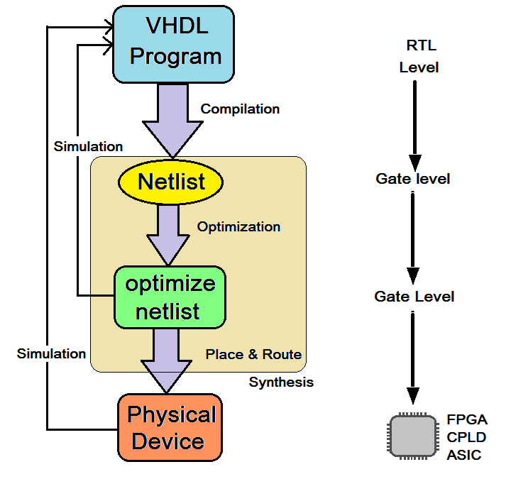
- VHDL design flow starts with writing the VHDL program. Various manufacturing companies like XILINX, Altera, etc. provide their own software development tools like XILINX ISE, Altera Quartus, etc. to edit, compile, and simulate VHDL code. In this VHDL code, the circuit is described in RTL (Resister Transfer Level)
- This VHDL code is compiled, and it generates Netlist at Gate level. The compiler converts high-level VHDL code in RTL to Gate Level
- This Netlist is further optimized to get optimized Netlist again at Gate Level. Optimization is done for better speed and less space. The simulation of design is done at this stage
- Finally, a physical device is implemented on CPLD / FPGA, or final MASK is prepared for ASIC from this optimize Netlist by place and route software (fitter). once again the final device can be simulated and verified
This is the digital circuit design flow using VHDL. Now because VHDL is also one kind of programming language, it also has its program structure (similar to other programming languages like C program structure). So as a next step, let us learn what the VHDL program structure is?
VHDL Program Structure
- All the VHDL programs consist of at least two components: Entity and Architecture
- It may have additional components like configuration, package declaration, body, etc. as per requirements
The structure of the VHDL program is like:
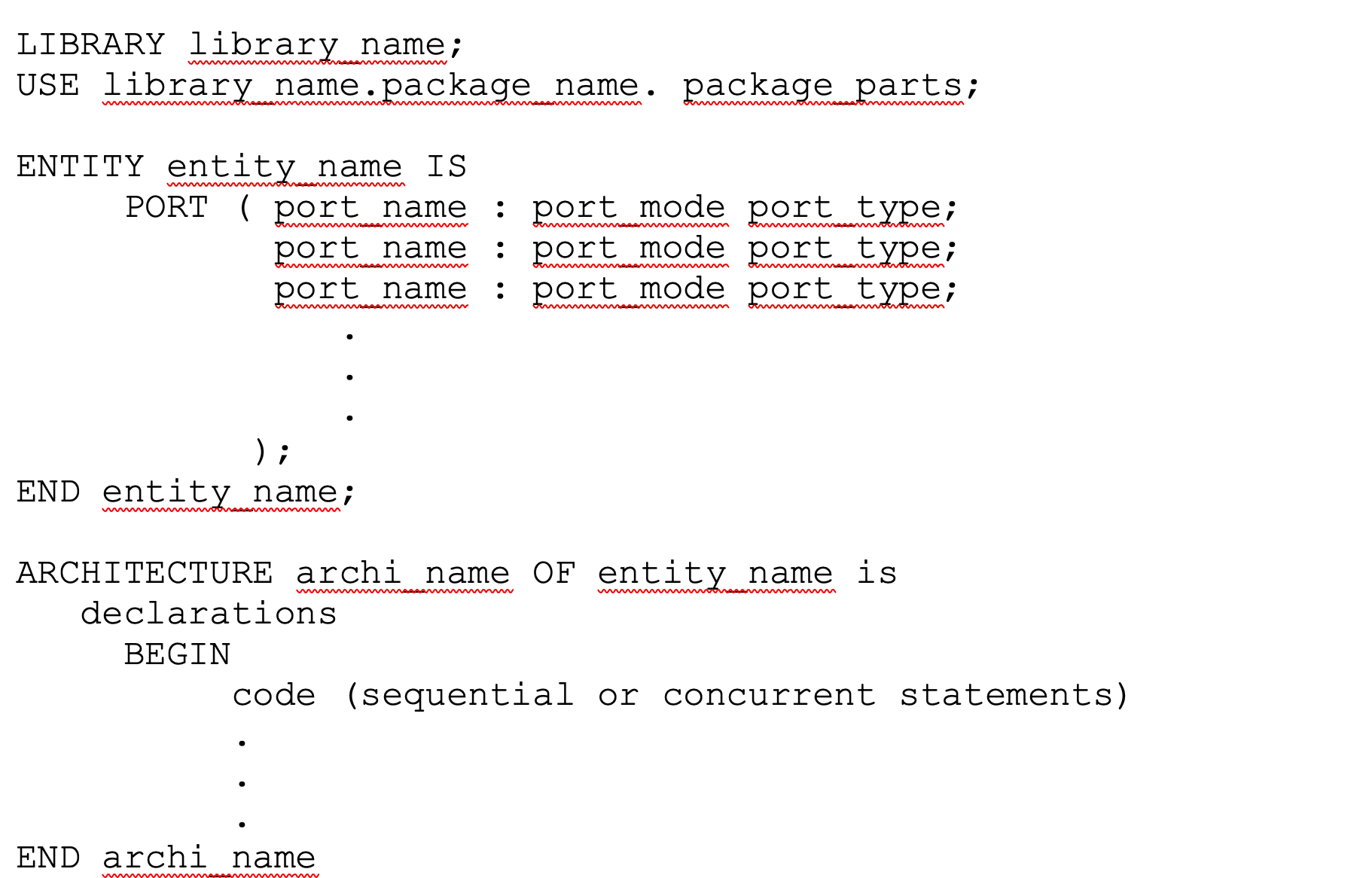 Library declaration:
- The library contains all the piece of code that is used frequently. It will allow us to reuse them again and again. Also, this can be shared with other designs
- It starts with keyword LIBRARY followed by library name
- There are three libraries usually used in all VHDL codes
- IEEE – specifies multilevel logic system
- std – resource library for VHDL design environment
- work – used for saving our project work and program file (.vhd)
- However, in program code, we need to declare only the IEEE library because the other two libraries are default libraries
- Now to add library packages and its part USE keyword is used with library name, library packages, and package parts. For example in the IEEE library, the package is std_logic_1164 and to add all its part we can write
LIBRARY ieee
USE ieee.std_logic_1164.all
- So all VHDL programs start with above two statements for library declaration
Entity declaration:
- Entity defines input-output connections of the digital circuit with which it can interact with other components/circuits
- It declares the number of inputs given to the circuit and the number of outputs taken out form the circuit.
- Also, it declares any intermediate signals that are used within the circuit itself.
- Entity declaration starts with the keyword ENTITY. The user has to give desire name to entity often related to a circuit that is being designed like ‘mux,’ ‘decoder,’ ‘adder,’ ‘counter’ etc. (the rule of thumb for any VHDL program is the program file name must be same as entity name)
- Inside entity, input-output pins of a circuit are declared using keyword PORT
- PORT (means interfacing pins) are declared with port_name, port_mode, and port_type
- port_name – it’s a user-defined name of the input-output pin
- port_mode – there are four types of port mode IN, OUT, INOUT and BUFFER. IN indicates an input pin, that can be read-only. OUT indicates an output pin and its write-only. Both these pins are unidirectional. INOUT pin is bidirectional that can be read as well as write. BUFFER is used for the intermediate output
- port_type – it can be BIT, BIT_VECTOR, STD_LOGIC, etc
- After declaring all interfaces, the entity declaration ends with keyword END followed by entity name
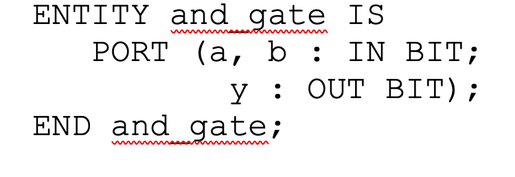
- Let us see an entity example for two-input AND gate.
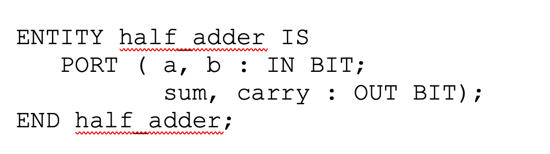
- Similarly, we can write an entity for half adder as
Architecture:
- Architecture declares the functionalities of the digital circuit
- It gives internal details of an entity that means how input-output are interconnected
- It describes behaviour of the circuit means how the circuit generates required output from given inputs
- The architecture declaration starts with keyword ARCHITECTURE followed by architecture_name and entity_name
- The BEGIN keyword indicates the starting of the architecture body. The body includes sequential or concurrent statements that describe circuit functionality
- The architecture body ends with keyword END followed by architecture_name
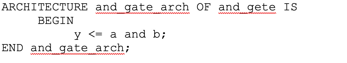
- Here is the architecture of 2 input AND gate (the entity is as given above).
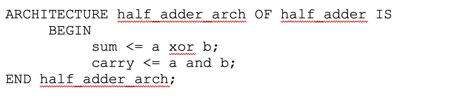
- Similarly, let us write architecture for half adder.
- There are three different modelling styles for architecture body
- Data flow style – in this modelling style the circuit is described using concurrent statements
- Behavioral style – in this modelling style the circuit is described using sequential statements
- Structural style – in this modelling style the circuit is described using different interconnected components
- There can be one more modelling style also that is mix modelling style – a combination of any two or all three styles given above
This completes the fundamentals of VHDL, its design flow, and program structure. In the next tutorial, we shall see different VHDL programs for digital circuits and different modelling styles for VHDL programs.
You may also like:


Filed Under: Tutorials, VHDL

Questions related to this article?
👉Ask and discuss on EDAboard.com and Electro-Tech-Online.com forums.
Tell Us What You Think!!
You must be logged in to post a comment.