Engineers Garage

  • Electronics Projects and Tutorials
    • Electronic Projects
      • Arduino Projects
      • AVR
      • Raspberry pi
      • ESP8266
      • BeagleBone
      • 8051 Microcontroller
      • ARM
      • PIC Microcontroller
      • STM32
    • Tutorials
      • Audio Electronics
      • Battery Management
      • Brainwave
      • Electric Vehicles
      • EMI/EMC/RFI
      • Hardware Filters
      • IoT tutorials
      • Power Tutorials
      • Python
      • Sensors
      • USB
      • VHDL
    • Circuit Design
    • Project Videos
    • Components
  • Articles
    • Tech Articles
    • Insight
    • Invention Stories
    • How to
    • What Is
  • News
    • Electronic Product News
    • Business News
    • Company/Start-up News
    • DIY Reviews
    • Guest Post
  • Forums
    • EDABoard.com
    • Electro-Tech-Online
    • EG Forum Archive
  • DigiKey Store
    • Cables, Wires
    • Connectors, Interconnect
    • Discrete
    • Electromechanical
    • Embedded Computers
    • Enclosures, Hardware, Office
    • Integrated Circuits (ICs)
    • Isolators
    • LED/Optoelectronics
    • Passive
    • Power, Circuit Protection
    • Programmers
    • RF, Wireless
    • Semiconductors
    • Sensors, Transducers
    • Test Products
    • Tools
  • Learn
    • eBooks/Tech Tips
    • Design Guides
    • Learning Center
    • Tech Toolboxes
    • Webinars & Digital Events
  • Resources
    • Digital Issues
    • EE Training Days
    • LEAP Awards
    • Podcasts
    • Webinars / Digital Events
    • White Papers
    • Engineering Diversity & Inclusion
    • DesignFast
  • Guest Post Guidelines
  • Advertise
  • Subscribe

Wireless Stepper Motor Speed Control using Laser and IC555

By Ashutosh Bhatt September 29, 2012

 
This is a very interesting application. We shall vary the speed of stepper motor from a remote place without any wire connection. I am using LASER and LDR for this purpose. From the transmitter, I will send low frequency pulses using LASER to the receiver. The LDR on receiver side will receive these pulses in form of LASER light. It will trigger monostable multi-vibrator to regenerate same pulses. These pulses will further drive the stepper motor through driver circuit. So as anyone changes pulse frequency from transmitter, the stepper motor speed will change accordingly 
 
Let us first see the block diagram of the system.
 
Block diagram:-
Block-diagram.jpg
 
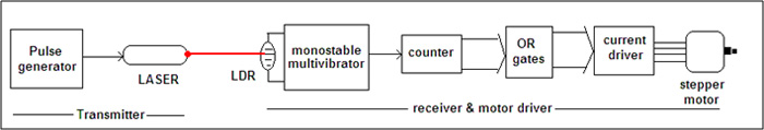
Pulse generator: – Its astable multi-vibrator using IC555 that generates variable low frequency pulses from 5 to 40 Hz
 
Laser: – The light output of LASER is modulated using output pulses of pulse generator. So light simply works as carrier for low frequency pulses
 
LDR: – It catches light signal and triggers monostable multi-vibrator
 
Monostable multi-vibrator: – It reproduces the pulses that is of same frequency as transmitter and give it to counter
 
Counter and OR gates: – Together these two will generate sequential pulses to drive the stepper motor properly
 
Current driver: – This will provide enough current to motor coil
 
Stepper Motor: – Its unipolar type stepper motor with max RPM of 200 – 250 and operating voltage of 5 VDC.
 

Circuit Diagram

Circuit Diagram:-
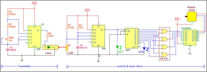
As shown in the tab, the circuit is divided in two different sections 1) transmitter and 2) receiver
Transmitter: – As I said earlier transmitter is astable multi-vibrator using IC555. If we calculate the minimum and maximum output pulse frequency depending upon given values of RC components then
 
formula.jpg
 
These low frequency pulses are directly given to LASER diode that generates LASER light beam. So actually LASER light is modulated with the help of these pulses. You may observe blinking LASER light effect when you apply 5 V supply to the circuit
 
Note: – The laser that I have used here is the laser key-chain readily available in the market. Just remove all button cells and cut the button cell section. Get the laser diode out and take out positive and negative (from outer body) connections. Now your LASER is ready to emit light beam through your circuit.
 
Receiver
Connections: – The first stage in the receiver side is the monostable multi-vibrator. The LDR along with 4.7K resistor used to trigger it. The output of monostable is given to clock input of counter. Its decade counter so there are 10 outputs O0 – O9. Out of these ten outputs 8 outputs are combined in group of 2 as O1-O4, O2-O5, O3-O6 and O4-O8 and applied to inputs of four OR gates as shown. All four consecutive outputs of OR gates are given as input to current driver chip ULN2003A. The four outputs of ULN are connected with four motor coil in sequence as RED-BLUE-WHITE-YELLOW. Two common terminals of motor (GREEN) are connected with Vcc.
 
Operation: – When LDR receives LASER light its resistance decreases. So the voltage on trigger i/p pin 2 will also decreases so we shall get output pulse from monostable. Time period of these pulse is to Small (1.1 ms) as compared to transmitted pulse (21 – 166 ms). So simply it will follow the period of transmitted pulse and generates same pulse as transmitted. This is indicated by GREEN LED. As these pulses are fed as clock input to decade counter its all ten outputs will produce pulse output one by one in sequence from O0 to O9. This counting is indicated by BLUE LED. Because outputs O0 to O3 and O4 to O8 are combined and given to inputs of OR gate we get four outputs to drive four stepper motor coils. Finally these four outputs are given as input to ULN chip which has built in NPN Darlington pair that will provide enough current to drive stepper motor coil and rotate motor. Thus motor rotates at the same frequency of transmitted pulse. As any one changes the frequency of transmitted pulse the motor RPM will also varies.
So this is how we may change the speed of stepper motor wirelessly using LASER. now if anyone wants to change the direction of stepper motor then it require slight modification in receiver circuit. the output from OR gates are given to inputs of ULN through DPDT switch as shown in given figure.
 
Operation.jpg
 

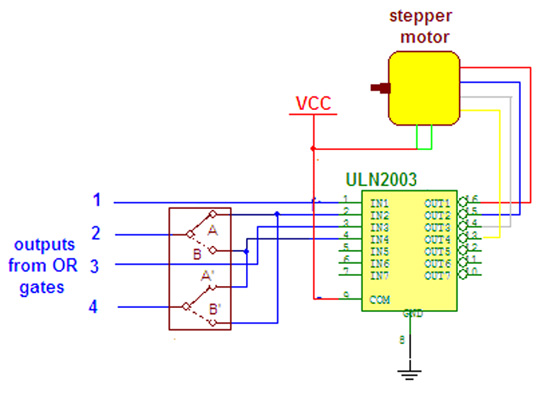
when switch is on position A-A’ then OR gate output 2 and 4 are given to inputs 2 and 4 of ULN chip and motor rotates in one direction. now as the switch is moved to position B-B’ the OR gate outputs 2 & 4 are interchanged and given to inputs 4 & 2 and motor changes its direction.


Video


Circuit Diagrams

Wireless-Stepper-Motor-Speed-Control


Filed Under: Electronic Projects
Tagged With: 555, ic, laser, motor, speed control, stepper motor
 

Next Article

← Previous Article
Next Article →

Questions related to this article?
👉Ask and discuss on Electro-Tech-Online.com and EDAboard.com forums.


Tell Us What You Think!! Cancel reply

You must be logged in to post a comment.

EE TECH TOOLBOX

“ee
Tech Toolbox: Internet of Things
Explore practical strategies for minimizing attack surfaces, managing memory efficiently, and securing firmware. Download now to ensure your IoT implementations remain secure, efficient, and future-ready.

EE Learning Center

EE Learning Center
“engineers
EXPAND YOUR KNOWLEDGE AND STAY CONNECTED
Get the latest info on technologies, tools and strategies for EE professionals.

HAVE A QUESTION?

Have a technical question about an article or other engineering questions? Check out our engineering forums EDABoard.com and Electro-Tech-Online.com where you can get those questions asked and answered by your peers!


RSS EDABOARD.com Discussions

  • SPI speed pic18f66j15
  • I/O constraint for Hold check
  • Inverting OpAmp - basic circuit question
  • Why does Synopsys DC need Inverters and Buffers if my RTL only has XOR logic?
  • GanFet power switch starts burning after 20 sec

RSS Electro-Tech-Online.com Discussions

  • LED circuit for 1/6 scale diorama
  • stud mount Schottky diodes
  • Hi Guys
  • using a RTC in SF basic
  • Can I use this charger in every country?

Featured – Designing of Audio Amplifiers part 9 series

  • Basics of Audio Amplifier – 1/9
  • Designing 250 Milli Watt Audio Power Amplifier – 2/9
  • Designing 1 Watt Audio Power Amplifier – 3/9
  • Designing a Bass Boost Amplifier – 4/9
  • Designing a 6 Watt Car Audio Amplifier – 5/9
  • Design a low power amplifier for headphones- 6/9

Recent Articles

  • Fischer connector system adds ratchet locking system designed for 300g shock resistance
  • Littelfuse introduces tactile switch with enhanced bracket peg design for mounting strength
  • Infineon releases GaN switch with monolithic bidirectional design
  • Sienna Semiconductor data converters feature sample rates from 20 to 250 Msps
  • Delta’s 5,500 W power supplies achieve 97.5% energy efficiency for AI servers

EE ENGINEERING TRAINING DAYS

engineering

Submit a Guest Post

submit a guest post
Engineers Garage
  • Analog IC TIps
  • Connector Tips
  • Battery Power Tips
  • DesignFast
  • EDABoard Forums
  • EE World Online
  • Electro-Tech-Online Forums
  • EV Engineering
  • Microcontroller Tips
  • Power Electronic Tips
  • Sensor Tips
  • Test and Measurement Tips
  • 5G Technology World
  • Subscribe to our newsletter
  • About Us
  • Contact Us
  • Advertise

Copyright © 2025 WTWH Media LLC. All Rights Reserved. The material on this site may not be reproduced, distributed, transmitted, cached or otherwise used, except with the prior written permission of WTWH Media
Privacy Policy

Search Engineers Garage

  • Electronics Projects and Tutorials
    • Electronic Projects
      • Arduino Projects
      • AVR
      • Raspberry pi
      • ESP8266
      • BeagleBone
      • 8051 Microcontroller
      • ARM
      • PIC Microcontroller
      • STM32
    • Tutorials
      • Audio Electronics
      • Battery Management
      • Brainwave
      • Electric Vehicles
      • EMI/EMC/RFI
      • Hardware Filters
      • IoT tutorials
      • Power Tutorials
      • Python
      • Sensors
      • USB
      • VHDL
    • Circuit Design
    • Project Videos
    • Components
  • Articles
    • Tech Articles
    • Insight
    • Invention Stories
    • How to
    • What Is
  • News
    • Electronic Product News
    • Business News
    • Company/Start-up News
    • DIY Reviews
    • Guest Post
  • Forums
    • EDABoard.com
    • Electro-Tech-Online
    • EG Forum Archive
  • DigiKey Store
    • Cables, Wires
    • Connectors, Interconnect
    • Discrete
    • Electromechanical
    • Embedded Computers
    • Enclosures, Hardware, Office
    • Integrated Circuits (ICs)
    • Isolators
    • LED/Optoelectronics
    • Passive
    • Power, Circuit Protection
    • Programmers
    • RF, Wireless
    • Semiconductors
    • Sensors, Transducers
    • Test Products
    • Tools
  • Learn
    • eBooks/Tech Tips
    • Design Guides
    • Learning Center
    • Tech Toolboxes
    • Webinars & Digital Events
  • Resources
    • Digital Issues
    • EE Training Days
    • LEAP Awards
    • Podcasts
    • Webinars / Digital Events
    • White Papers
    • Engineering Diversity & Inclusion
    • DesignFast
  • Guest Post Guidelines
  • Advertise
  • Subscribe