Typical electronic voting machines require voters to push a button to cast their ballots. However, there have been security concerns with these devices and whether they’re at risk for tampering. One solution is to use biometric-based voting machines, which use fingerprint matching or a retina scan to verify an authorized voter.
In this project, we’ll develop a biometric voting machine based on a person’s fingerprint. We’ll build the device using Arduino Mega, with a 3.5-inch TFT touchscreen and R307 fingerprint module. The touchscreen will be the user interface for the “voter” to cast their ballot.
Required components
- Arduino Mega x1
- 3.5-inch TFT touchscreen for Arduino x1
- R307 fingerprint sensor x1
Circuit connections
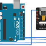
To build a biometric voting machine, we must first interface the 3.5-inch TFT touchscreen and R307 fingerprint sensor with Arduino Mega. The touchscreen is an Arduino shield that fits over the board.
To interface the fingerprint sensor:
- Connect the R307 sensor’s VCC and GND pins with Arduino’s 5Vout and ground pins.
- Connect the R307 sensor’s TX and RX pins with Arduino’s RX1 and TX1.
The circuit connections are shown in the diagram below.

Uploading the fingerprints
After making circuit connections, we must “enroll” the fingerprints of valid voters. Upload the following sketch in Arduino MEAG and a single fingerprint of each voter.
To learn more about interfacing the R307 sensor, and how to enroll and match fingerprints on it, check out this project.
Preparing the voting machine
After the authorized voters’ fingerprints have been enrolled, it’s time to prepare the voting machine to receive ballots. We’ll use the 3.5-inch TFT touchscreen as the user interface.
To calibrate the touchscreen:
- Install the Adafruit_GFX.h and MCUFRIEND_kbv.h libraries to Arduino IDE
- Navigate to File-> Examples -> MCUFRIEND_kbv -> Touchscreen_Calibr_native

- Upload the example sketch to Arduino Mega.
- Open Arduino IDE’s Serial Monitor and touch the corner points on the touchscreen as indicated by the + signs using a stylus.
You must note down the values for XP, XM, YP, YM, TS_LEFT,TS_RT, TS_TOP, and TS_BOT. It’s important to copy these values from the Serial Monitor and save them in a text file for later use.
For our touchscreen, the variables were found to have the following values:
- const int XP=6,XM=A2,YP=A1,YM=7; //320×480 ID=0x9486
- const int TS_LEFT=931,TS_RT=168,TS_TOP=452,TS_BOT=191;
Next, upload the following sketch in Arduino Mega, so it functions as a biometric voting machine.
How it works
The first uploaded sketch sets up an “admin” on Arduino IDE’s Serial Monitor for enrolling the fingerprints of authorized voters. The R307 fingerprint sensor allows up to 128 fingerprints indexed from 0 to 127.
The machine must be prepared for voting next by calibrating the touchscreen using the example sketch. After the final sketch is uploaded, Arduino resets. It then displays the user interface where voters can select one of three candidates.
When a voter presses the button on the touchscreen beside their preferred candidate, another screen appears on the TFT display, prompting a fingerprint scan. The voter must place their index finger on the fingerprint sensor. The sensor will flash an LED, capturing an image of their fingerprint.
If the fingerprint matches with an enrolled print, the vote is counted, and a screen thanking the voter appears on the TFT display. If the voter is not enrolled, the message “Sorry, you cannot vote.” will appear on the TFT display.
Afterward, the main screen reappears, allowing others to cast their ballots.
The code
The main sketch begins by importing Adafruit_GFX.h, MCUFRIEND_kbv.h, TouchScreen.h, and EEPROM.h libraries. The Adafruit_GFX.h and MCUFRIEND_kbv.h are required to operate the 3.5-inch TFT display. The TouchScreen.h is required for the touchscreen to function as a voting device. The EEPROM.h library is used to store the votes in the Arduino’s EEPROM memory.
The following lines of code define the serial port for communication with the R307 sensor, instantiating an object for the proper fingerprint matching.
#include <Adafruit_Fingerprint.h>
#if (defined(__AVR__) || defined(ESP8266)) && !defined(__AVR_ATmega2560__)
SoftwareSerial mySerial(2, 3);
#else
#define mySerial Serial1
#endif
Adafruit_Fingerprint finger = Adafruit_Fingerprint(&mySerial);
This is followed by defining variables, which store the total number of votes for the three candidates. The following lines of code define the color constants for the TFT display and instantiate a display object.
#define BLACK 0x0000
#define BLUE 0x001F
#define RED 0xF800
#define GREEN 0x07E0
#define CYAN 0x07FF
#define MAGENTA 0xF81F
#define YELLOW 0xFFE0
#define WHITE 0xFFFF
MCUFRIEND_kbv tft
Next, the constants are defined for the touchscreen function and the instantiation of a touch object.
#define MINPRESSURE 10
#define MAXPRESSURE 1000
const int XP=6,XM=A2,YP=A1,YM=7; //320×480 ID=0x9486
const int TS_LEFT=931,TS_RT=168,TS_TOP=452,TS_BOT=191;
#define TS_MINX 125
#define TS_MINY 85
#define TS_MAXX 965
#define TS_MAXY 905
TouchScreen ts(XP, YP, XM, YM, 300); //re-initialised after diagnose
TSPoint tp; //global point
In the setup() function, the TFT screen is initialized using following code.
tft.reset();
tft.begin(tft.readID());
tft.setRotation(2);
The fingerprint sensor is initialized using the following lines of code in the setup() function.
Serial.begin(9600);
Serial.println();
Serial.print(“reading id…”);
delay(500);
Serial.println(tft.readID(), HEX);
finger.begin(57600);
delay(5);
if (finger.verifyPassword()) {
Serial.println(“Found fingerprint sensor!”);
}
else {
Serial.println(“Did not find fingerprint sensor :(“);
while (1) { delay(1); }
}
Finally, the voter’s user interface for voting is displayed on the TFT screen, using the following.
tft.fillScreen(BLACK);
Home();
pinMode(13, OUTPUT);
result();
The Home() function defines and displays the main screen of the voting machine, where voters can cast their vote for one of the three candidates.
void Home()
{
tft.fillScreen(BLACK);
tft.drawRoundRect(0, 0, 320, 480, 8, WHITE); //Page border
tft.setCursor(105, 5);
tft.setTextSize(3);
tft.setTextColor(CYAN);
tft.print(“Voting”);
tft.setCursor(97, 29);
tft.print(“Machine”);
tft.drawRoundRect(35, 70, 250, 50, 8, WHITE); //Vote
tft.fillRoundRect(35, 70, 250, 50, 8, YELLOW);
tft.setTextSize(3);
tft.setTextColor(WHITE);
tft.setCursor(60, 82);
tft.print(“Candidate 1”);
tft.drawRoundRect(35, 160, 250, 50, 8, WHITE); //Enroll
tft.fillRoundRect(35, 160, 250, 50, 8, YELLOW);
tft.setCursor(60, 172);
tft.print(“Candidate 2”);
tft.drawRoundRect(35, 250, 250, 50, 8, WHITE);
tft.fillRoundRect(35, 250, 250, 50, 8, YELLOW); //Result
tft.setCursor(60, 262);
tft.print(“Candidate 3”);
}
The user interface is defined according to the 3.5-inch TFT touchscreen’s resolution, which is 480×320 pixels.
Screen1() defines the user interface screen, prompting a voter to scan their index finger for authentication.
void screen1()
{
tft.fillScreen(BLACK);
tft.setTextSize(3);
tft.setTextColor(WHITE);
tft.setCursor(70, 190);
tft.print(“Please Scan”);
tft.setCursor(70, 240);
tft.print(“Your Finger”);
Serial.println(“Please press finger”);
}
Screen2() defines the user interface, which appears when the user is not validated as an enrolled voter.
void screen2()
{
Serial.println(“Finger not found”);
tft.fillScreen(BLACK);
tft.setTextSize(3);
tft.setCursor(70, 190);
tft.print(“Sorry You”);
tft.setCursor(70, 240);
tft.print(“Can’t Vote”);
delay(3000);
Home();
}
The fingerprintMatch() function scans and matches fingerprints on call and returns TRUE if the fingerprint is matched, and FALSE if it’s not.
bool fingerprintMatch(){
screen1();
delay(5000);
uint8_t p = finger.getImage();
if (p == FINGERPRINT_NOFINGER) goto NoFinger;
else if (p == FINGERPRINT_OK) {
p = finger.image2Tz();
if (p != FINGERPRINT_OK) goto NoMatch;
p = finger.fingerFastSearch();
if (p != FINGERPRINT_OK) goto NoMatch;
Serial.print(“Verified ID:”);
Serial.println(finger.fingerID);
delay(1500);
return true;
}
NoMatch:
{
return false;
}
NoFinger:
{
Serial.println(“No finger detected”);
delay(1500);
return false;
}
}
In the loop() function, a HIGH-to-LOW signal is sent on the GPIO13 pin interfaced with the touchscreen to initiate touch sensing. An object for the touch function is initialized. If the pressure exerted by the voter on the touchscreen is above a specific threshold, the pixel positions are mapped.
During the testing phase, these pixel positions are printed to the Serial console to determine the exact touch points for the buttons (in the user interface) for the three candidates. Later, these lines of code are commented.
digitalWrite(13, HIGH);
digitalWrite(13, LOW);
TSPoint p = ts.getPoint();
// if sharing pins, you’ll need to fix the directions of the touchscreen pins
//pinMode(XP, OUTPUT);
//pinMode(YM, OUTPUT);
pinMode(XM, OUTPUT);
pinMode(YP, OUTPUT);
if (p.z > ts.pressureThreshhold)
{
p.x = map(p.x, TS_MAXX, TS_MINX, 0, 320);
p.y = map(p.y, TS_MAXY, TS_MINY, 0, 240);
//Serial.print(“X:”); // I used this to get the accurate touch points for X and Y axis
//Serial.print(p.x);
//Serial.print(” “);
//Serial.print(“Y:”);
//Serial.println(p.y);
If the touch points correspond to ‘candidate1,’ the voter’s fingerprint is verified to complete the voting process. The display returns to the voting window whether the vote is accepted (and valid) or rejected.
if (p.x > 50 && p.x < 280 && p.y > 160 && p.y < 190 && p.z > MINPRESSURE && p.z < MAXPRESSURE)
{
Serial.println(“Candidate 1”);
if(fingerprintMatch())
{
vote1++;
EEPROM.write(0, vote1);
tft.fillScreen(BLACK);
tft.setCursor(70, 220);
tft.print(“Thank You”);
delay(3000);
Home();
}
else
{
screen2();
}
}
The same is done for other two candidates. The voting results are printed to Serial console on a reset as the results are saved in EEPROM. The results are calculated by the results() function.
void result()
{
vote1=EEPROM.read(0);
vote2=EEPROM.read(1);
vote3=EEPROM.read(2);
int vote=vote1+vote2+vote3;
Serial.println(vote1);
Serial.println(vote2);
Serial.println(vote3);
if(vote)
{
if((vote1 > vote2 && vote1 > vote3))
{
Serial.print(“Candidate 1 Wins”);
delay(2000);
}
else if(vote2 > vote1 && vote2 > vote3)
{
Serial.print(“Candidate 2 Wins”);
delay(2000);
}
else if((vote3 > vote1 && vote3 > vote2))
{
Serial.print(“Candidate 3 Wins”);
delay(2000);
}
else
{
Serial.print(“Tie Up Or”);
Serial.print(“No Result”);
delay(1000);
}
}
else
{
Serial.print(“No Voting….”);
delay(1000);
}
}
Results

Demonstration video:
Below is a screenshot of the voting process in the Serial console for the above demonstration.

You may also like:


Filed Under: Arduino., Electronic Projects, Video

Questions related to this article?
👉Ask and discuss on EDAboard.com and Electro-Tech-Online.com forums.
Tell Us What You Think!!
You must be logged in to post a comment.