In the previous tutorial, we discussed multiplexing seven-segment displays (SSDs). Continuing with the display devices, in this tutorial, we will cover how to interface character LCD when using Arduino. Character LCDs are the most common display devices used in embedded systems. These low-cost LCDs are widely used in industrial and consumer applications.
Display devices in embedded systems
Most devices require some sort of display for various reasons. For example, an air-conditioner requires a display that indicates the temperature and AC settings. A microwave oven requires a display to present the selected timer, temperature, and cooking options. A car dashboard uses a display to track distance, fuel indication, mileage, and fuel efficiency. Even a digital watch requires a display to showcase the time, date, alarm, and modes.
There are also several reasons industrial machinery and electrical or electronic devices require a display.
The display devices used in embedded circuits — whether they are industrial devices, consumer electronic products, or fancy gadgets — are used either to indicate some information or to facilitate machine-human interface.
For instance, LEDs are used as indicators of mutually exclusive conditions. The SSDs are used to display numeric information. The Liquid Crystal Displays (LCDs), TFTs, and OLED displays are used to present the more complicated information in embedded applications. Often, this complication arises due to the text or graphical nature of the information or the interface.
LCDs are the most common display devices used in all sorts of embedded applications. There are two types of LCD displays available:
1. Character LCDs
2. Graphical LCDs.
The character LCDs are used where the information or interface is of a textual nature. The graphical LCDs are used where the information or interface is of a graphical nature. The graphical LCDs that are used to design machine-human interfaces may also have touchscreens.
Character LCDs
Character LCDs are useful in showing textual information or to provide a text-based, machine-human interface. It’s even possible to display some minimal graphics on these LCDs. These are low-cost LCD displays that fit in a wide range of embedded applications.
Generally, character LCDs do not have touchscreens. And unlike graphical LCDs, these LCDs do not have continuous pixels. Instead, the pixels on character LCDs are arranged as a group of pixels or dot-matrix of pixels of fixed dimensions.
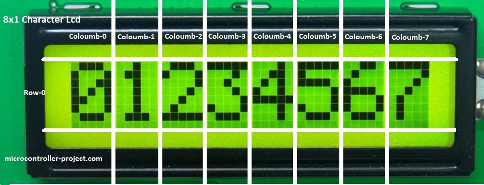
Each dot-matrix of a pixel is intended to display a text character. This group of pixels is usually of 5×7, 5×8, or 5×10 dimensions — where the first digit indicates the number of columns of pixels and the second digit indicates the number of rows of pixels. For example, if each character has 5×8 dimensions, then the character is displayed by illuminating 5 columns and 8 rows of pixels/dots. This may include pixels used to show the cursor.
The character LCDs are classified by their size, which is expressed as the number of characters that can be displayed. The number of possible characters that can display at a time on the LCD is indicated as the number of columns of characters and the number of rows of characters.
The common size of character LCDs is 8×1, 8×2, 10×2, 16×1, 16×2, 16×4, 20×2, 20×4, 24×2, 30×2, 32×2, 40×2, etc. For example, a 16×2 character LCD can display 32 characters at a time in 16 columns and 2 rows. Generally, characters are displayed as a matrix of black dots while the backlight of LCD may be a monochromatic color like blue, white, amber, or yellow-green.


LCDs are available as one of three types:
1. Twisted Nematic (TN)
2. Super Twisted Nematic (STN)
3. Focus Super Twisted Nematic (FSTN).
The character LCDs may use any one of these types. The TN types are low-cost but have a narrow viewing angle and low contrast. The FSTN offers the best contrast and widest viewing angle, but they are more costly. Even character LCDs that use the FSTN display are still cheaper in comparison to graphical LCDs, TFTs, and OLEDs.
Most of the character LCDs use LED backlight and the backlight color can be white, blue, amber, or yellow-green. The other types of a backlight in character LCDs include EL, CCFL, internal power, external power, and 3.3 and 5V backlights. EL and LED backlights are the most common. The LCD may have a reflective, trans-reflective, or transmissive rear polarizer.
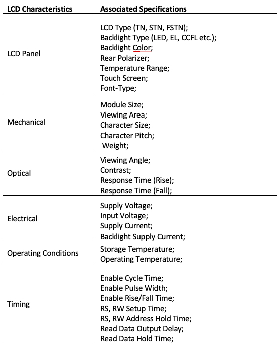
The quality of display depends on the LCD type, the backlight, and the nature of a rear polarizer used in the LCD panel. When selecting an LCD panel for an embedded application, it’s important to decide on the quality of the LCD display, according to the requirements. This includes per the application, class of the device, nature of use (such as indoor or outdoor), target users of the device, intended user-experience, operating conditions (such as temperature and operating voltage), and cost limitations.
For example, a character LCD that has to be used for the machine-human interface must have better contrast, a wide viewing angle, and a good backlight.
The following table summarizes the important characteristics of any character LCD.
Even on a character LCD, a large number of pixels have to be controlled to display the text. A 16×2 character LCD in which each character is 5×8 pixels means that a total of 1280 pixels (16×2 characters x 5×8 Pixels) have to be controlled. This requires interfacing the pixels across 16 rows (2 rows of characters x 8 rows in each character) and 80 columns (16 columns of characters x 5 columns in each character) of connections.
This is when pixels are black dots and merely require switching either ON or OFF by the controller to display text characters. On a typical microcontroller, there are not these many I/O pins that can be dedicated to controlling the pixels of an LCD panel. That is why LCD modules have integrated controllers that control the pixels of the LCD. The integrated controller can interface with a microcontroller or a processor via an 8-bit/4-bit parallel port or a serial interface (like I2C). The integrated controller receives data and commands from the microcontroller/processor to display text on the LCD panel via a 4-bit/8-bit parallel or serial interface.
In fact, the LCD module is a complete embedded system comprising of an LCD panel, LCD driver, LCD controller, LED Backlight, internal flags, Address Counter, Display Data RAM (DDRAM), Character Generator ROM (CGROM), Character Generator RAM (CGRAM), Data Register (DR), Instruction Register (IR), and Cursor Control Circuit.
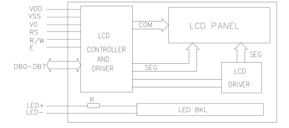
Functional blocks of the LCD module
A character LCD module has these functional blocks:
1. LCD Panel. The character LCDs have the dot-matrix LCD panel. The text characters are displayed on the panel according to the commands and data received by the integrated controller.
2. System Interface. This module has a 4-bit and an 8-bit interface to connect with microcontrollers/processors. Some LCD modules also have a built-in serial interface (I2C) for communication with a controller. The selection of interface (4-bit or 8-bit) is determined by the DL bit of the Instruction Register (IR).
3. Data Register (DR). Data Register is an internal register that stores data received by the microcontroller via the system interface. The value populated in the data register is compared with character patterns in Character Generator ROM (CGROM) to generate different standard characters.
4. Instruction Register (IR). Instruction Register is an internal register that stores instructions received by the microcontroller via the system interface.
5. Character Generator ROM (CGROM). It’s an internal Read-Only Memory (ROM) on the LCD module where the patterns for the standard characters are stored. For example, a 16×2 LCD module, CGROM has 5×8 dots, 204 character patterns, and 5×10 dots of 32 characters pattern that are stored. So, the patterns for the 204 characters are permanently stored in the CGROM.
6. Character Generator RAM (CGRAM). The user-defined characters can also be displayed on a character LCD. The patterns for custom characters are stored in CGRAM. On the 16×2 LCD, 5 characters of the 5×8 pixels can be defined by a user program. The user needs to write the font data (which is the character pattern defining what pixels/dots must ON and which must OFF to properly display the character) to generate these characters.
7. Display Data RAM (DDRAM). The data sent to the LCD module by the microcontroller remains stored in DDRAM. In 16×2 character LCD, DDRAM can store a maximum of 80 8-bit characters where the maximum of 40 characters for each row can be stored.

8. Address Counter (AC). The Address Counter is an internal register that stores DDRAM/CGRAM addresses that are transferred by the Instruction register. The AC reads the DDRAM/CGRAM addresses from bits DB0-DB6 of the instruction register. After writing into the DDRAM/CGRAM, the AC is automatically increased by one, while after reading from the DDRAM/CGRAM, the AC is automatically decreased by one.
9. Busy Flag (BF). The bit DB7 of the instruction register is a busy flag of the LCD module. When the LCD is performing some internal operations, this flag is set (HIGH). During this time, the instruction register does not accept any new instruction via the system interface from the microcontroller. New instructions can be written to the IR but only when the busy flag is clear (LOW).
10. Cursor/Blink Control Circuit. This controls the ON/OFF status of the cursor/blink at the cursor position. The cursor appears at the DDRAM address currently set in the AC. For example, if the AC is set to 07H, then the cursor is displayed at the DDRAM address 07H.
11. LCD Driver. It controls the LCD panel and the display. In the 16×2 character LCD, the LCD driver circuit consists of 16 common signal drivers and 40 segment signal drivers.
12. Timing Generation Circuit. It generates the timing signals for the operation of internal circuits, such as the DDRAM, CGRAM, and CGROM. The timing signals for reading RAM (DDRAM/CGRAM) module are generated separately to display characters and timing signals for the internal operations of the integrated controller/processor of LCD. This is so that the display does not interfere with the internal operations of the integrated controller of the LCD module.
Interfacing character LCDs
Most of the character LCDs have a 14-pin or 16-pin system interface for communication with a microcontroller/processor. The 16-pin system interface is the most common.
It has this pin configuration:
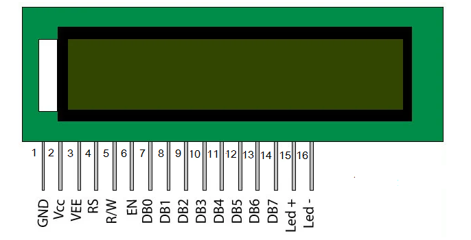
The pin descriptions of the LCD module’s system interface are summarized in this table:
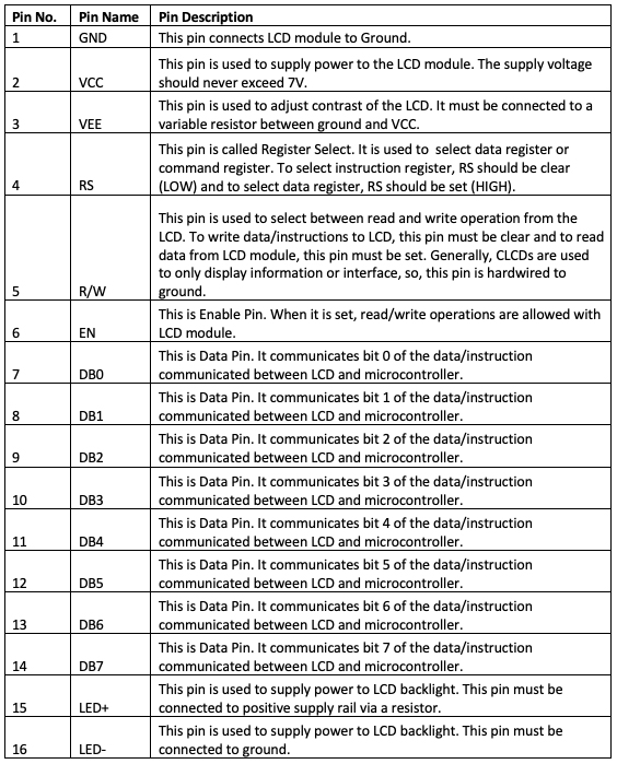
To interface the LCD module with a microcontroller or Arduino, the digital I/O pins of the microcontroller must be connected with the RS, RW, EN, and data pins DB0 to DB7.
Typically, Arduino (or any microcontroller) does not need to read data from the LCD module, so the RW pin can be hard-wired to ground.
- If the LCD is interfaced with Arduino in an 8-bit mode, the RS, EN, and all of the data pins must be connected to the digital I/O pins of Arduino.
- If the LCD is interfaced with Arduino in 4-bit mode, the RS, EN, and the data bits DB7 to DB4 must be connected to Arduino’s GPIO.
In 4-bit mode, two pulses are required at the EN pin to write data/instruction to the LCD. At first, the higher nibble of data or the instruction is latched. Then, in the second pulse lower nibble of the data/instruction is transferred.
In an 8-bit mode, the entire 8-bit data/instruction is written to the LCD in a single pulse at the EN pin. So, the 4-bit mode saves the microcontroller pins but has a slight latency in comparison to the 8-bit mode of operation. The 8-bit mode suffers less from latency but engages 4 extra pins from the microcontroller.
It’s also possible to interface the LCD module with Arduino using a serial-to-parallel converter. Then, only two pins of Arduino are required to interface with the LCD module.
The ground pin of the LCD module (pin 1) must be connected to the ground while the VCC pin (pin 2) must be connected to the supply voltage. The 3.3 or 5V pin of Arduino can be used to supply voltage to the LCD module. The VEE pin must be connected to the variable terminal of a variable resistor, and the fixed terminals of the variable resistor must be connected to the VCC and ground.
The LED+ (pin 15) must be connected to the VCC via a current-limiting resistor and the LED (pin 16) must be connected to the ground.
How character LCD works
It is possible to read/write data with the LCD module. To write data/instructions to the LCD module, the RW pin must be clear. Then, if the RS is set, an 8-bit data sent by the microcontroller stores in the data register (DR) of the LCD module. This 8-bit data sent by the microcontroller will store in the instruction register (IR) of the LCD module.
The data is transferred to the LCD from the microcontroller when a HIGH to LOW pulse is applied at the EN pin of the module.
When data is sent to the LCD module (RW=0, RS=1, EN=1->0), it is written in the DDRAM and the Address Counter of the LCD is increased by one. The LCD controller compares the 8-bit data with the CGROM addresses and displays the appropriate character on the LCD at the associated DDRAM address. This serves as the instruction to show that the display has been received.
When the instruction is sent to the LCD module (RW=0, RS=0, EN=1->0), it is stored in the instruction register and according to the pre-defined instruction set of the LCD controller, the appropriate operation is executed on the display (to set display ON, set display OFF, set cursor ON, set cursor OFF, clear DDRAM, etc.).
Sometimes, the microcontroller may need to read data from the LCD. A microcontroller can read content from the instruction register, DDRAM, and CGRAM of the LCD. To read data from the LCD, the RW pin must be set. When the RW is set and the RS is clear, the microcontroller reads the content of Instruction Register (IR) — including the busy flag (DB7 of IR) and address counter (DB6 to DB0 of IR) — when applying a HIGH to LOW pulse at EN pin.
When the RW is set and the RS is set, the microcontroller reads the content of the DDRAM or CGRAM according to the current value of the address counter when applying a HIGH to LOW pulse at EN pin.
So, the microcontroller reads the content of the instruction register when: RW=1, RS=0, and EN=1->0.
It reads the content of the DDRAM/CGRAM at the current address counter when: RW=1, RS=1, and EN=1->0.
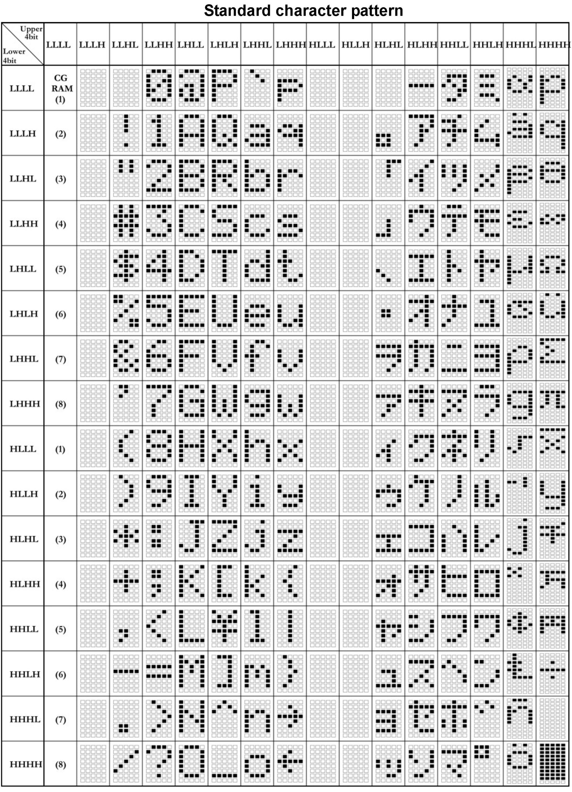
LCD characters set
The following characters, with the given patterns and data register values, are supported on a 16×2 LCD.
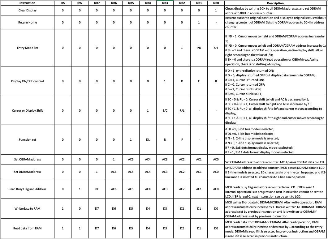
LCD commands
A 16×2 LCD module supports the following an 8-bit commands:
LCD functions using Arduino
If the LCD module is interfaced to typical microcontrollers (8051, PIC, AVR, etc.), the RS, RW, EN, and the data bits need to be set individually to perform the read/write operations.
Arduino has a Liquid Crystal library (LiquidCrystal.h) available that makes programming LCD with Arduino extremely easy. This library can be imported by the following statement:
#include <LiquidCrystal.h>
The library uses these methods to control a character LCD:
1. LiquidCrystal()
2. lcd.begin()
3. lcd.clear()
4. lcd.home()
5. lcd.setCursor(col, row)
6. lcd.write(data)
7. lcd.print(data)/lcd.print(data, BASE)
8. lcd.cursor()
9. lcd.noCursor()
10. lcd.blink()
11. lcd.noBlink()
12. lcd.display()
13. lcd.noDisplay()
14. lcd.scrollDisplayLeft()
15. lcd.scrollDisplayRight()
16. lcd.autoscroll()
17. lcd.noAutoscroll()
18. lcd.leftToRight()
19. lcd.rightToLeft()
20. lcd.createChar(num, data)
LiquidCrystal() method
This method is used to create a Liquid Crystal object. The object must be created according to the circuit connections of the LCD module when using Arduino.
The object takes the pin numbers of the Arduino as arguments. The pin numbers where the RS, RW, EN, and the data pins (DB7-DB0 for 8-bit mode and DB7-DB4 for 4-bit mode) of the LCD are connected, has to be passed as arguments in the object definition.
This method has this syntax:
If the LCD is connected in a 4-bit mode and the R/W pin is grounded:
LiquidCrystal(rs, enable, d4, d5, d6, d7);
or
LiquidCrystal lcd(rs, enable, d4, d5, d6, d7);
If the LCD is connected in a 4-bit mode and the R/W pin is also connected to Arduino:
LiquidCrystal(rs, rw, enable, d4, d5, d6, d7);
or
LiquidCrystal lcd(rs, rw, enable, d4, d5, d6, d7);
If the LCD is connected in an 8-bit mode and the R/W pin is grounded:
LiquidCrystal(rs, enable, d0, d1, d2, d3, d4, d5, d6, d7);
or
LiquidCrystal lcd(rs, enable, d0, d1, d2, d3, d4, d5, d6, d7);
If the LCD is connected in an 8-bit mode and the R/W pin is connected to Arduino:
LiquidCrystal(rs, rw, enable, d0, d1, d2, d3, d4, d5, d6, d7);
or
LiquidCrystal lcd(rs, rw, enable, d0, d1, d2, d3, d4, d5, d6, d7);
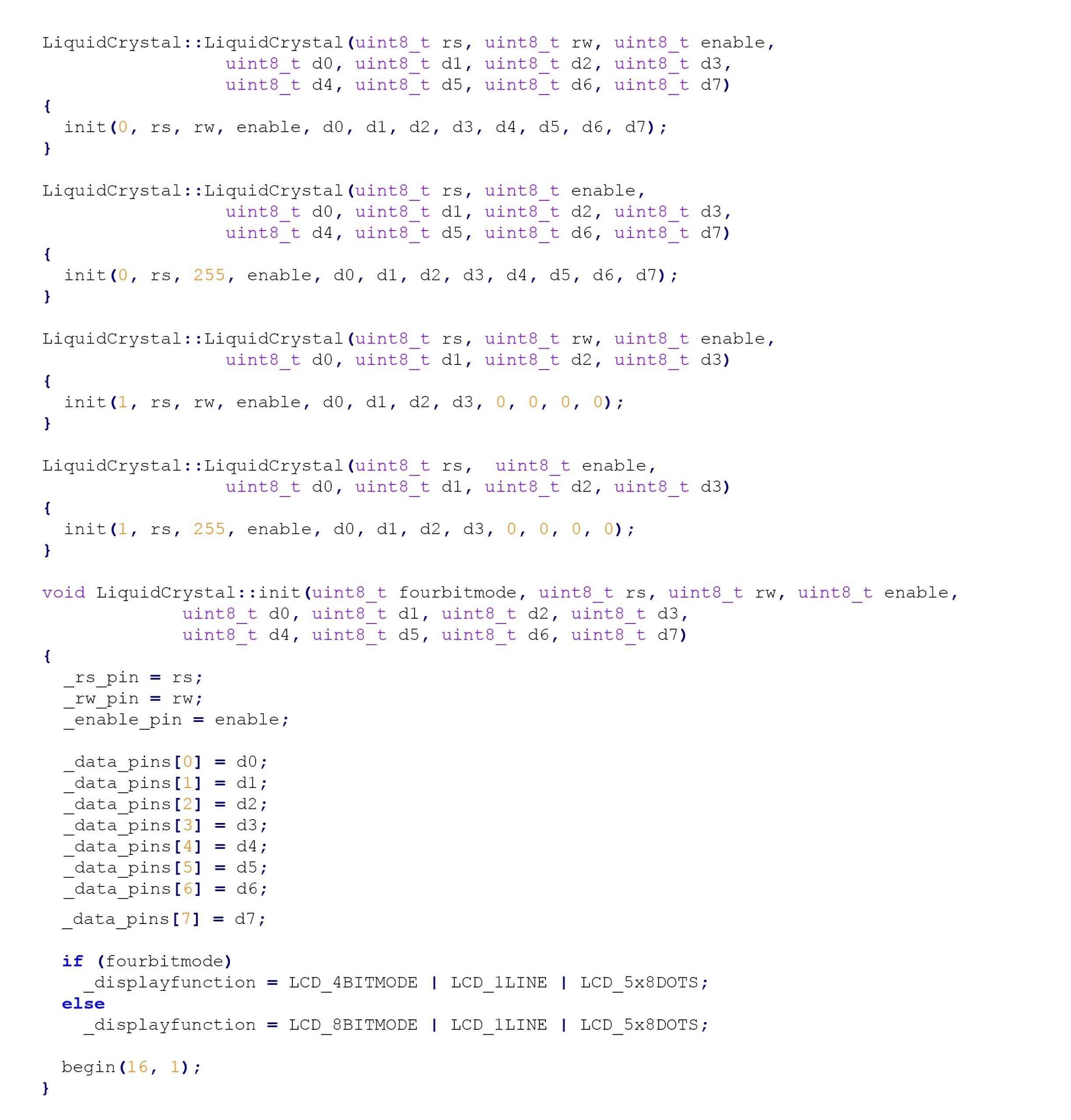
The LiquidCrystal class has this source code:
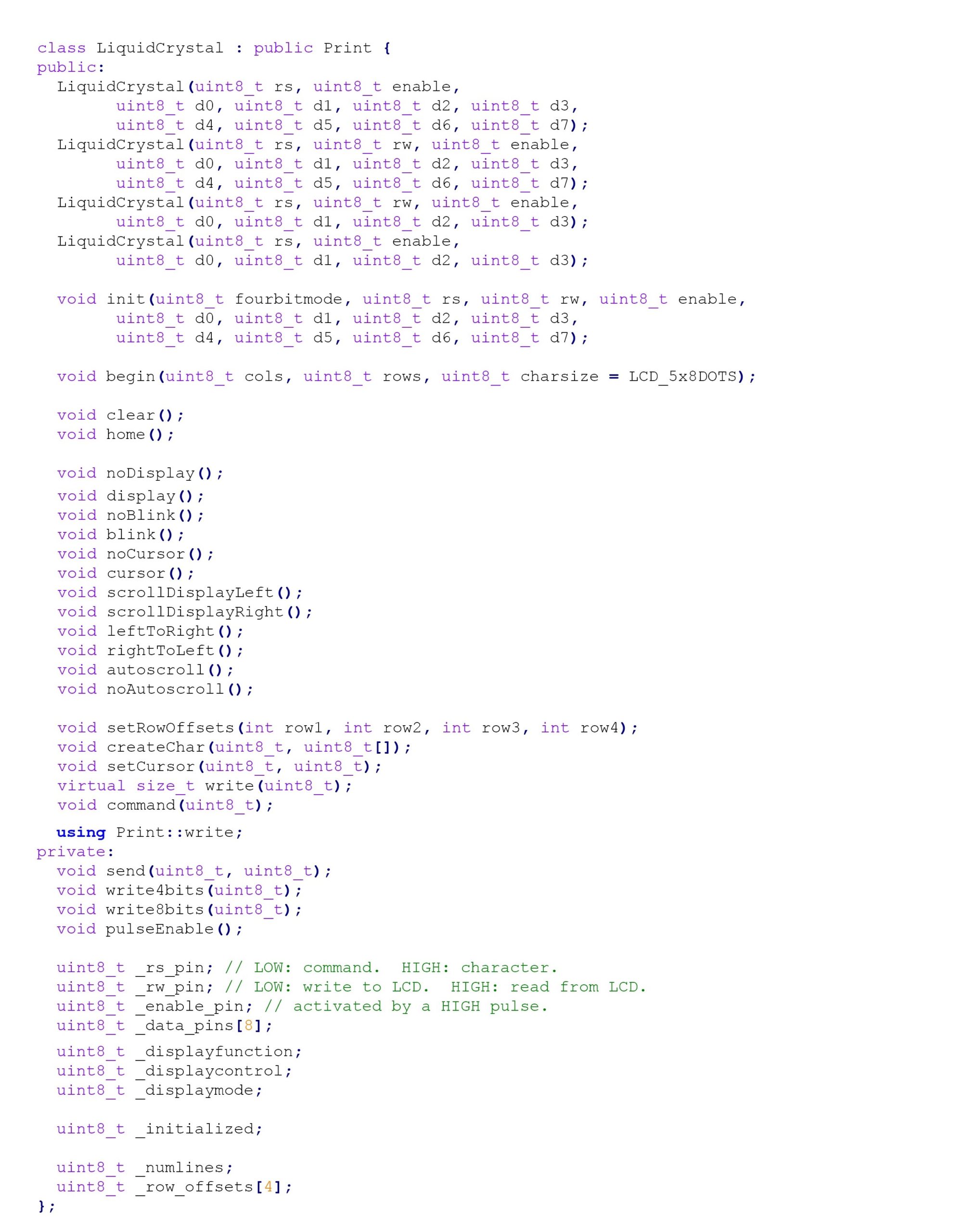
The LiquidCrystal method has this definition in the source code:
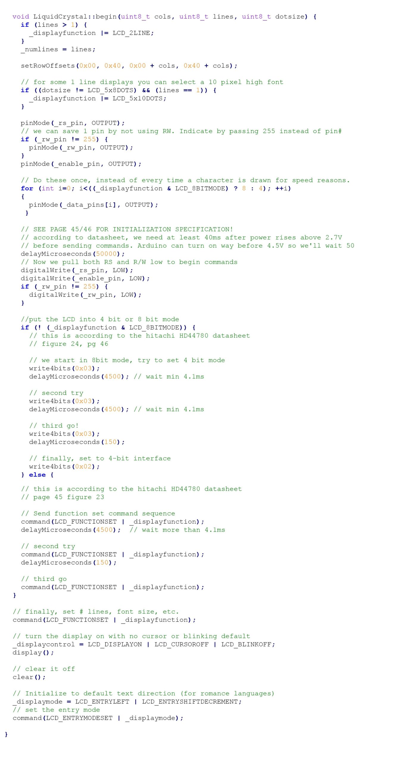
lcd.begin() method
This method is used to initialize the LCD module. The function takes the size of the LCD (expressed by number of columns and rows in the LCD) as the arguments.
It has this syntax:
lcd.begin(cols, rows)
This function has the following source code:
lcd.clear() method
This method clears the LCD display and positions the cursor to the top-left corner.
It has this syntax:
lcd.clear()
This function has the following source code:
![]()
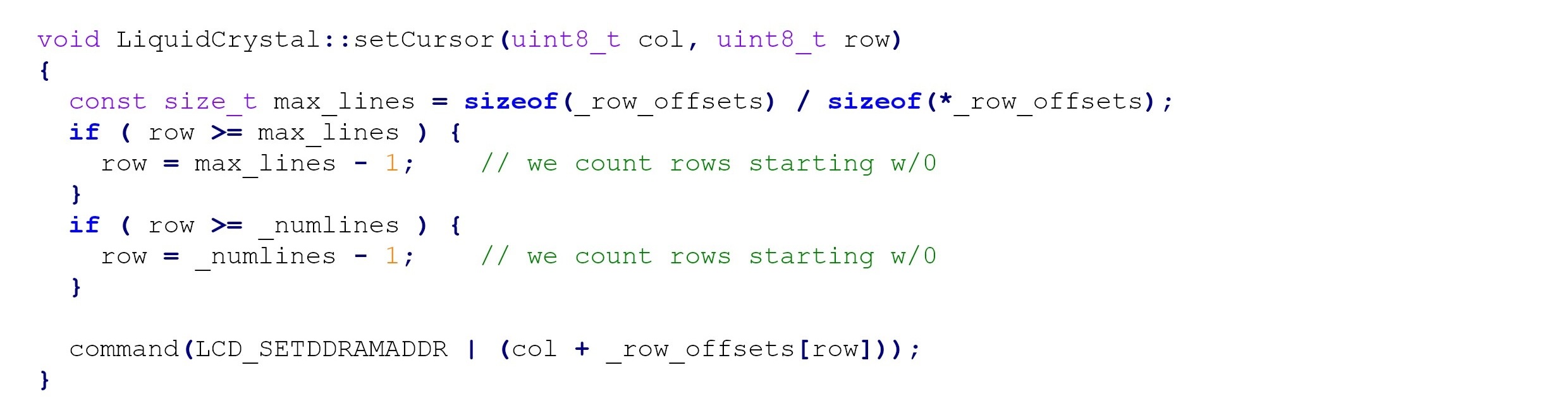
lcd.setCursor() method
This method positions the cursor at the given location on the LCD panel. It takes the column and row as the argument where the cursor has to be placed and a subsequent character has to be displayed.
It has this syntax:
lcd.setCursor(col, row)
This method has the following source code:
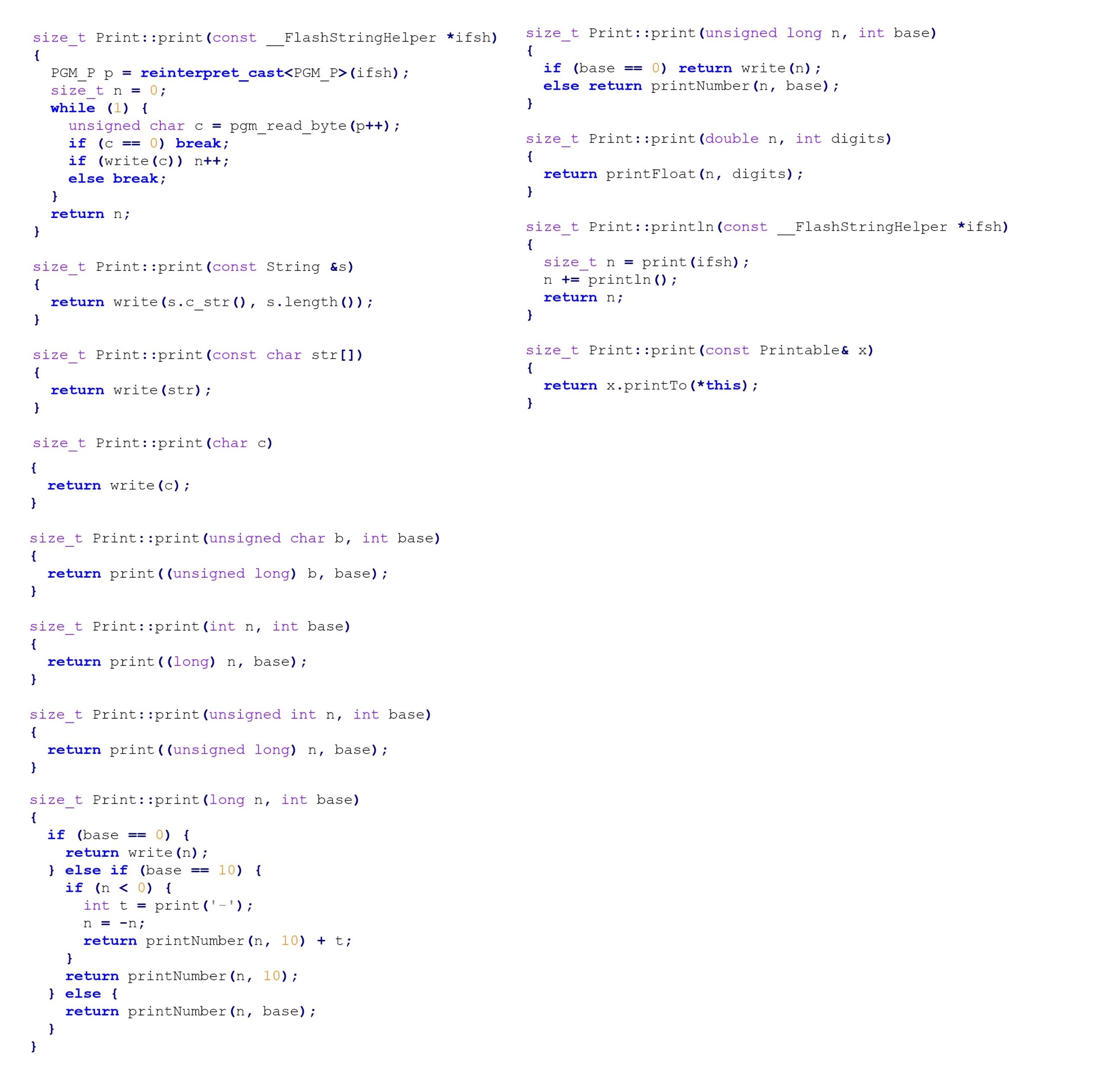
lcd.print() method
This method is used to print text to the LCD. It takes a string argument, which has to be displayed at the current cursor position on the LCD. It can take base of the value passed as an optional argument — if only printing numbers.
It has this syntax:
lcd.print(data)
lcd.print(data, BASE)
This method comes from Print.h library that is included in the LiquidCrystal.h library.
This method has the following source code:
How to check the LCD
A common concern when interfacing the LCD module is to identify whether or not the LCD module is, indeed, working. When connecting the LCD with Arduino (or any other MCU), if only the lower line of the LCD brightens, then the LCD module is working.
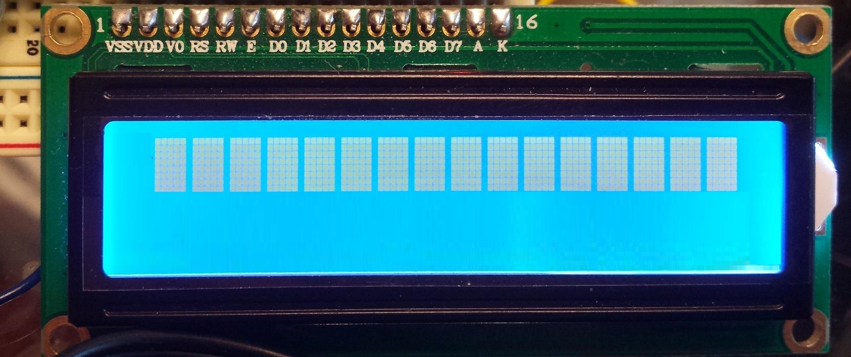
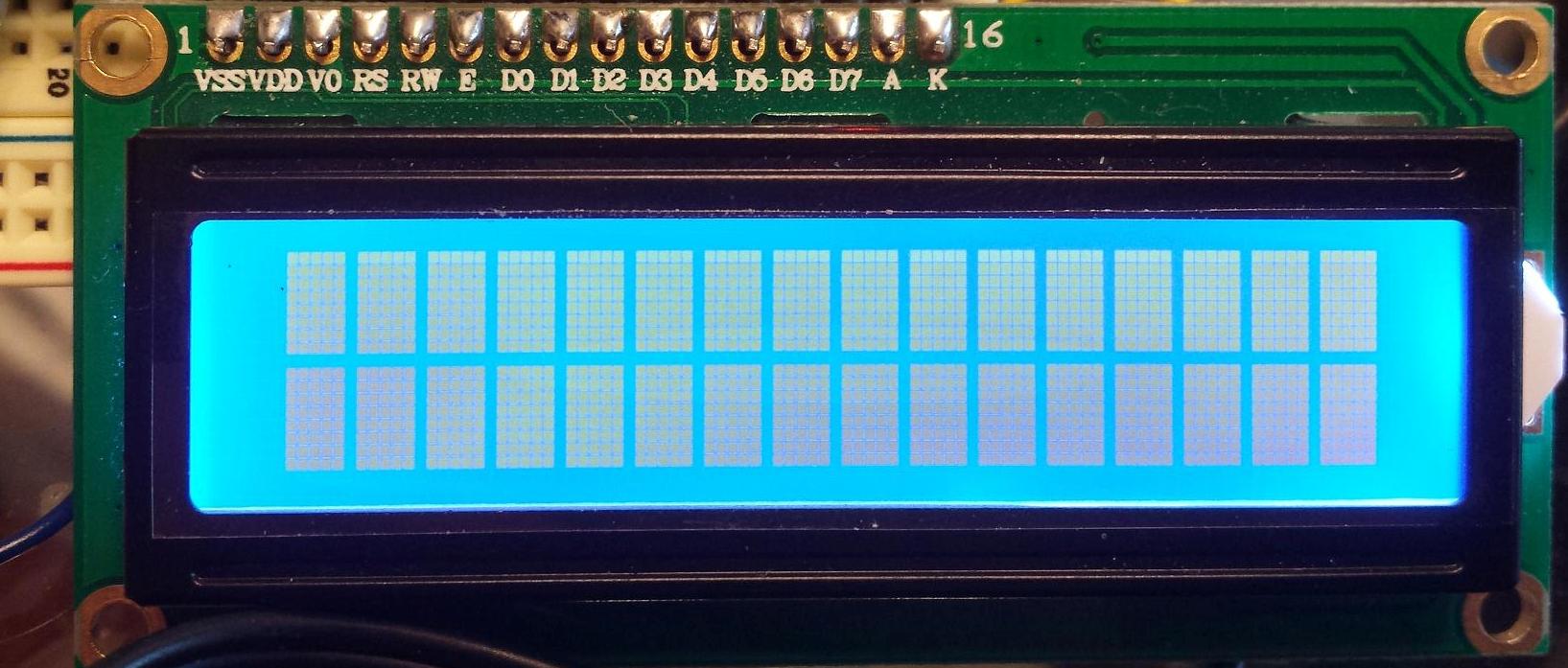
When connecting LCD with Arduino, if both lines of the LCD (16×2 LCD) brightens, then the LCD is not working properly.
Sometimes when you try to print on the LCD, nothing occurs, except the lower line of the LCD illuminating. In this case, the possible reasons can be one of the following:
1. There may be loose connections between Arduino (MCU) and the LCD module.
2. The LCD module might have been interfaced in the reverse pin order (i.e. instead of pins 1 to 16, circuit connections might have been made from pins 16 to 1 of the LCD module).
3. There may be shorting between LCD terminals due to faulty soldering.
4. The contrast of the LCD at the VEE pin might not have been adjusted properly. If the adjustment of contrast does not work, try connecting the VEE pin directly to the ground, so that the LCD module is adjusted to maximum contrast.
5. If after checking all the circuit connections, LCD panel still does not display text, check if the code uploaded to Arduino is correct or not. For example, it is possible that if the LCD display is not cleared after initialization, garbage values may display on the LCD instead of the intended text.
Recipe: Printing text on the 16X2 character LCD
In this tutorial, we will print simple text on the 16×2 LCD panel from Arduino UNO.
Components required
1. Arduino UNO x1
2. 16×2 character LCD x1
3. 10K Pot x1
4. 330 Ohms Resistor or any low-value resistor x1
5. Breadboard x1
6. Male-to-Male Jumper Wires or Connecting Wires
Circuit connections
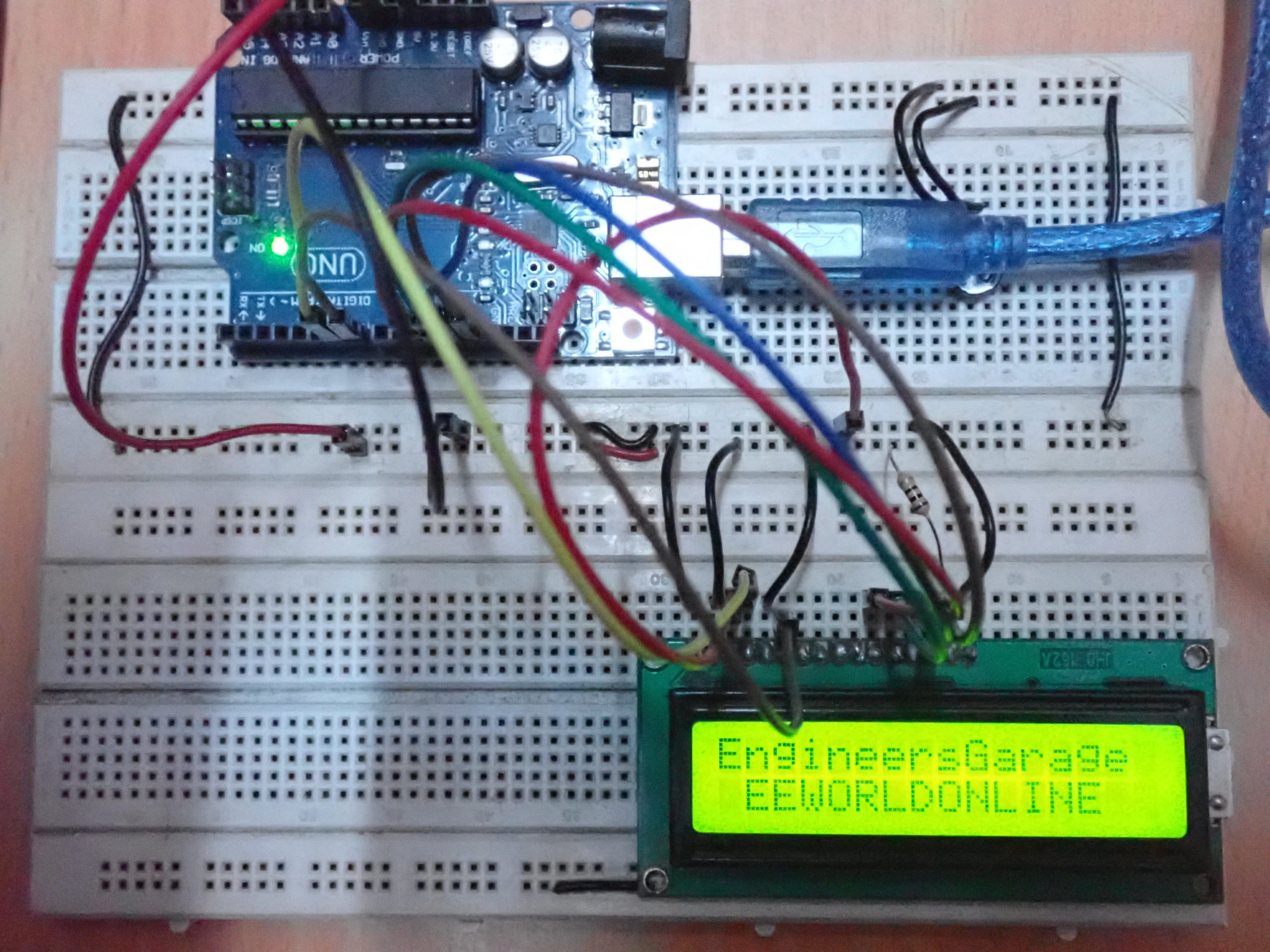
The LCD module used in this project is JHD162A. This is a 16×2 LCD module with 5×8 character dots. The LCD module has a 16-pin interface. The LCD is interfaced with Arduino in 4-bit mode.
Pin 1 (GND) and 16 (LED) of the LCD module are connected to ground while pin 2 (VCC) is connected to the VCC. The pin 15 (LED+) from the LCD module is, once again, connected to the VCC via a small-value resistor. The pin 3 (VEE) is connected to the variable terminal of a pot while the fixed terminals of the pot are connected to the ground and VCC.
The R/W pin is connected to the ground as Arduino will only write data to the LCD module. The RS, EN, DB4, DB5, DB6, and DB7 pins of the LCD are connected to pins 13, 11, 7, 6, 5, and 4 of Arduino UNO, respectively. The breadboard supplies the common ground. The 5V supplies the rail from one of the ground pins and 5V pin of the Arduino UNO, respectively.
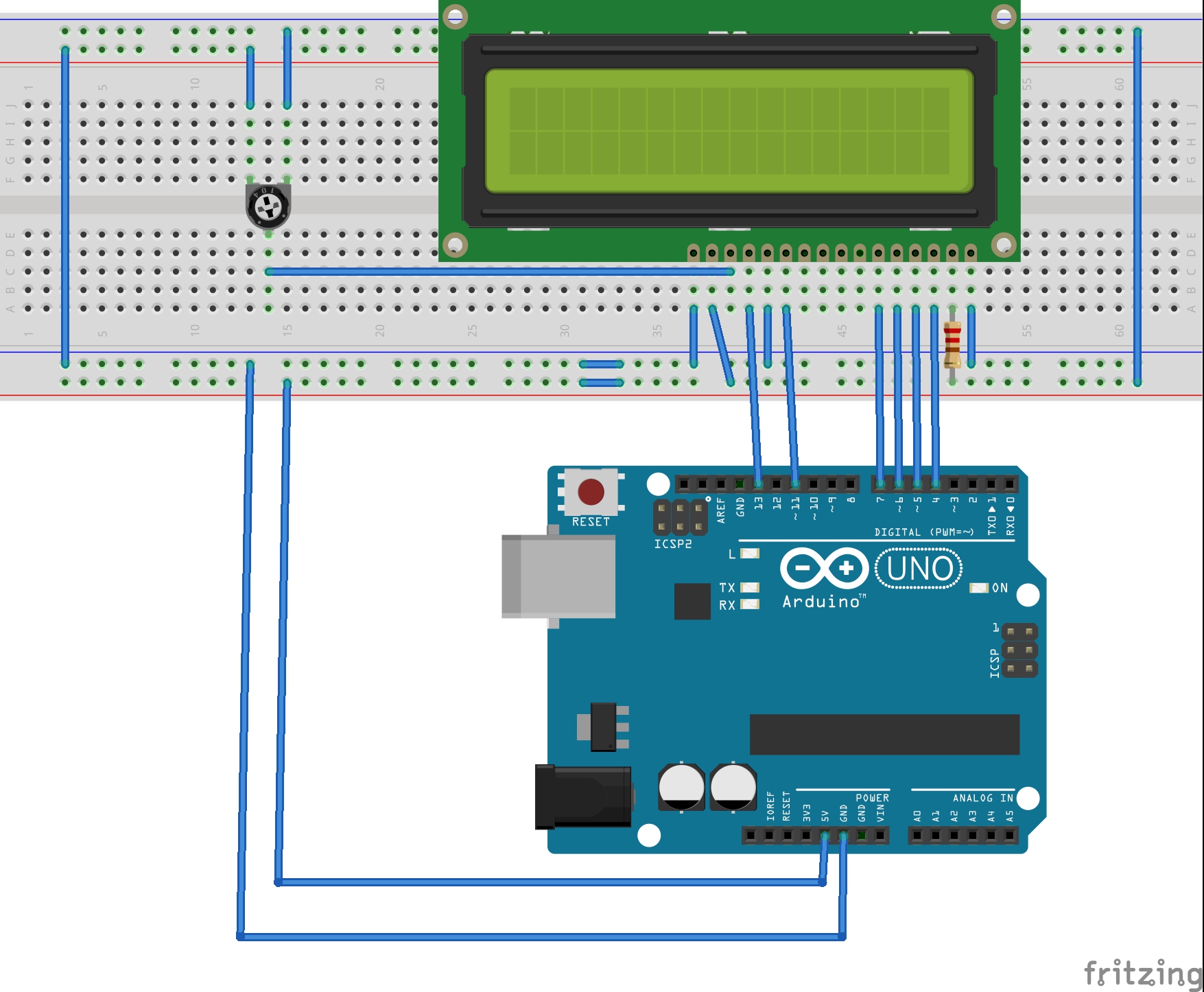
Circuit diagram

Arduino sketch
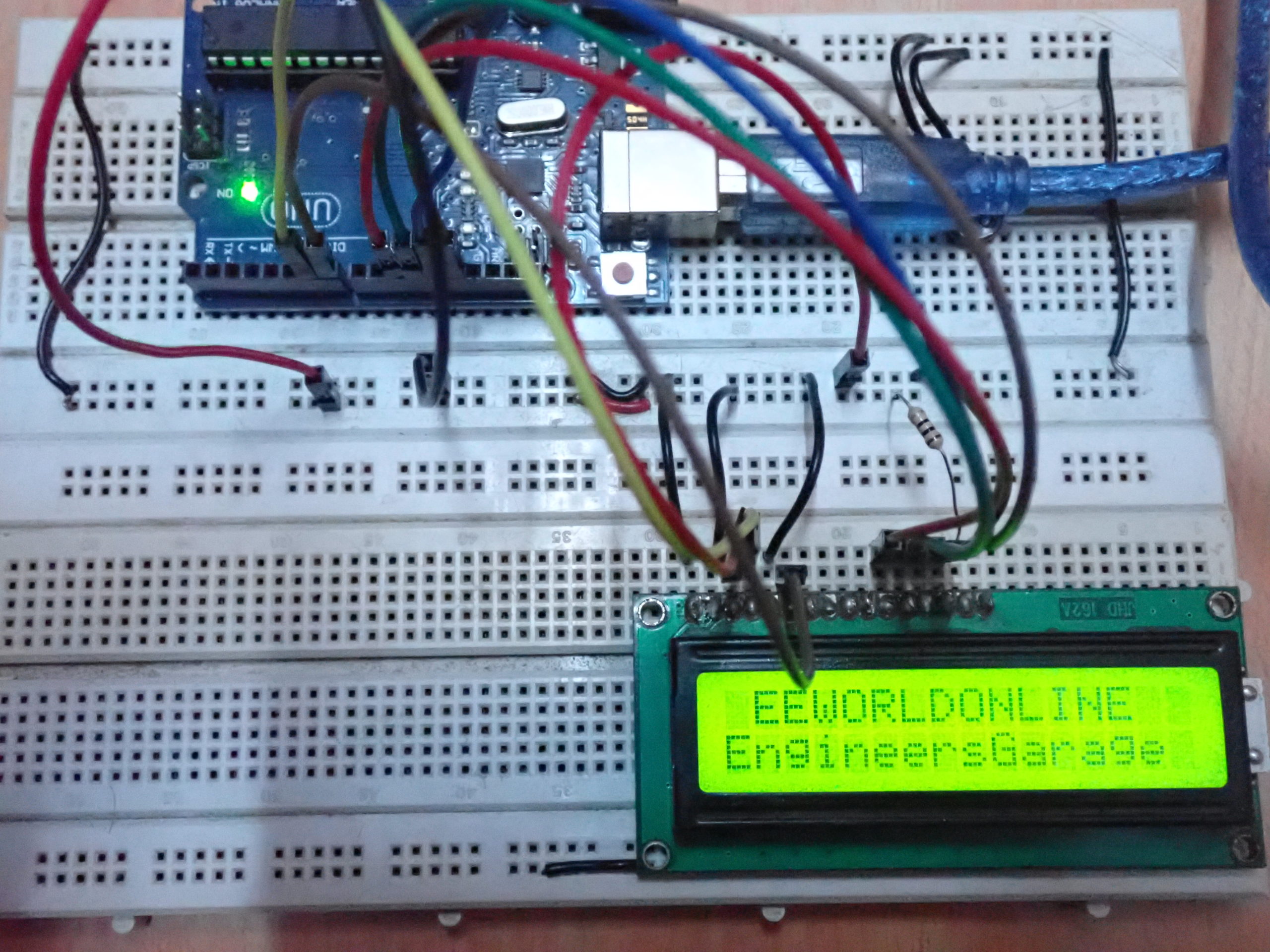
How the project works
The LCD module is connected with Arduino in a 4-bit mode. First, the LCD is initialized and the display is cleared to get rid of any garbage values in the DDRAM. The cursor is set to column 1 of the line 0, and the text, “EEWORLDONLINE” is printed on LCD.
Next, the cursor is moved to column 0 of line 1 and text, “EngineersGarage” is printed on the LCD. A delay of 750 milliseconds is given and the LCD is cleared again.
The cursor is moved to column 0 of the line 0 and the text, “EngineersGarage” is printed on the LCD. The cursor is then moved to column 1 of line 1 and text, “EEWORLDONLINE” is printed on the LCD.
Arduino UNO will keep repeating the code and, alternatively, printing both of the text strings on the lines 0 and 1.
Programming guide
The LiquidCrystal.h library is imported in the code. Then, an object defined by the variable “lcd” is defined for the LiquidCrystal class.
#include <LiquidCrystal.h>
//LiquidCrystal lcd(RS, E, D4, D5, D6, D7);
LiquidCrystal lcd(13, 11, 7, 6, 5, 4);
In the setup() function, the LCD is initialized to the 16×2-size, using the begin() method like this:
void setup()
{
lcd.begin(16, 2);
}
In the loop() function, the LCD display is cleared using the clear() method and he cursor is set at column 1 of line 0 by using the setCursor() method. The text “EEWORLDONLINE” is printed using the print() method on the “lcd” object. Similarly, the text “EngineersGarage” is printed at column 0 of line 1. A delay of 750 milliseconds is given by using the delay() function.
void loop()
{
lcd.clear();
lcd.setCursor(1, 0);
lcd.print(“EEWORLDONLINE”);
lcd.setCursor(0, 1);
lcd.print(“EngineersGarage”);
delay(750);
Next, the LCD display is cleared again and the position of both texts is inversed.
lcd.clear();
lcd.setCursor(0, 0);
lcd.print(“EngineersGarage”);
lcd.setCursor(1, 1);
lcd.print(“EEWORLDONLINE”);
delay(750);
}
The body of the loop() function will keep repeating itself until Arduino is shutdown. Therefore, both texts keep displaying on the LCD module, alternating their position between line 0 and 1 of the panel.
In the next tutorial, we will discuss how to use scrolling text on the LCD module.
You may also like:


Filed Under: Arduino, Tutorials

Questions related to this article?
👉Ask and discuss on Electro-Tech-Online.com and EDAboard.com forums.
Tell Us What You Think!!
You must be logged in to post a comment.