RGB LED is a combination of three LEDs red-green-blue together. It has four terminals – either anode or cathode, and the other three are for these three colors. Interestingly, when two colors inside the LED are turned ON simultaneously, the LED gives a different color. Also, as the amount or intensity of any color in LED varies, the resulting color is entirely different. So by combining different colors and mixing red, green, and blue colors, many other colors can be generated.
The given project uses an Arduino microcontroller development board to vary the intensity (amount) of red, green, or blue color by generating a PWM output wave. The width of the PWM wave is varied as per the potentiometer varied connected to the analog input pin. It uses three potentiometers to vary the intensity of red, green, and blue colors. By setting pots to different values, different amounts of red – green – blue can be set, resulting in one complete new color. So let us see how it is done. First, collect required components and other equipment.
Required components and equipment
- Arduino UNO/NANO development board
- Two RGB LEDs – common anode type
- Three 10 K potentiometer
- Breadboard
- Connecting wires
Circuit diagram
Description
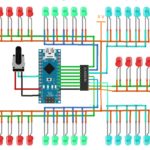
The figure shows that three potentiometers and two RGB LEDs are connected to the Arduino board.
- Two end terminals of all three pots are shorted and connected to Vcc and gnd
- As shown, the middle sliding terminals are connected to analog input pins A4, A5, and A6 of the Arduino board.
- The anode terminals of both RGB LEDs are connected to a 5V supply through a current limiting resistor of 330Ω.
- Analog outputs 3, 5, and 6 are connected to red, green, and blue inputs of RGB LED 2, respectively, and the other three analog outputs 9, 10, and 11 are connected to red, green, and blue inputs of RGB LED 1
Here is the snap of the circuit arrangement.
Operation
- The three pots are named red_pot (R_pot), green_pot (G_pot), and blue_pot (g_pot) that will vary the intensity of red color, green color, and blue color, respectively.
- These three pots will vary the width of analog outputs at pins 3, 5, 6, 9, 10 and 11
- When R_pot is varied, the pulse width on analog output pins 3 and 9. As the pot increases, the pulse width at pin 3 increases, and at pin 9, it decreases and vice versa.
- The red color intensity will vary because these two are red LED inputs of RGB LED1 and RGB LED 2.
- Similarly, when G_pot is varied, the pulse width of pins 5 and 10 will vary. This will vary the green color intensity in both LEDs
- And finally, when B_pot is varied, the pulse width of pins 6 and 11 will vary, and the blue color intensity will vary.
- Thus as the three pots are varied, it will vary the amount of (intensity) of red-green-blue colors, and this mixture of red-green and blue colors will generate different colors like yellow, orange, cyan, pink, white, etc.
Software program
This operation is based on the program loaded into the Arduino board through the Arduino IDE software tool. The following program is compiled and uploaded into an internal flash of onboard microcontroller, the ATMega328.
Youtube video link for this project
You may also like:
Filed Under: Electronic Projects, Featured



Questions related to this article?
👉Ask and discuss on EDAboard.com and Electro-Tech-Online.com forums.
Tell Us What You Think!!
You must be logged in to post a comment.