Engineers Garage

  • Projects and Tutorials
    • Electronic Projects
      • 8051
      • Arduino
      • ARM
      • AVR
      • PIC
      • Raspberry pi
      • STM32
    • Tutorials
    • Circuit Design
    • Project Videos
    • Components
  • Articles
    • Tech Articles
    • Insight
    • Invention Stories
    • How to
    • What Is
  • News
    • Electronic Products News
    • DIY Reviews
    • Guest Post
  • Forums
    • EDABoard.com
    • Electro-Tech-Online
    • EG Forum Archive
  • Digi-Key Store
    • Cables, Wires
    • Connectors, Interconnect
    • Discrete
    • Electromechanical
    • Embedded Computers
    • Enclosures, Hardware, Office
    • Integrated Circuits (ICs)
    • Isolators
    • LED/Optoelectronics
    • Passive
    • Power, Circuit Protection
    • Programmers
    • RF, Wireless
    • Semiconductors
    • Sensors, Transducers
    • Test Products
    • Tools
  • EE Resources
    • DesignFast
    • LEAP Awards
    • Oscilloscope Product Finder
    • White Papers
    • Webinars
  • EE Learning Center
    • Design Guides
      • WiFi & the IOT Design Guide
      • Microcontrollers Design Guide
      • State of the Art Inductors Design Guide
  • Women in Engineering

Generating Different Colours from RGB LED using Arduino PWM

By Deepesh Verma


Prototype of Arduino based RGB LED Controller

Fig. 1: Prototype of Arduino based RGB LED Controller

RGB-LED is widely used to generate different colour Lights in Interior Decoration, Electronic Appliances, Automobiles, etc.

This article deals with Arduino to get various colours with RGB LED and show the transition from one colour to another.

The PWM output of an Arduino, is an important tool to get the variety of colours, be it Pink, Cyan, Magenta, Orange, Purple, etc.

An RGB LED is a four terminal LED with one common pin (say cathode) and three other pins (anode) for Red, Green and Blue LEDs.

Pin Diagram and Internal Circuit of RGB LED

Fig. 2: Pin Diagram and Internal Circuit of RGB LED

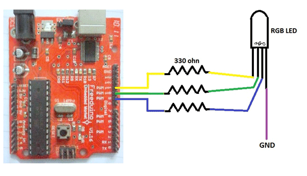
The first step, getting and RGB LED and testing it. For this we need to connect 5V supply to bare LED through Resistors (330ohms).

Now that we have got RED, GREEN and BLUE colours individually, its time to get a mix of these three basic colours.

Get an Arduino (any basic board with at least 3 PWM outputs). I used an Atmega8 one.

Connect your Arduino, do proper connections, as shown in below circuit diagram.

Proceeding further, it’s now time to get the control over the LED. We’ll do this through Arduino-IDE.

Go to Arduino-IDE, select your board type, under the ‘Tools’ menu. Select COM port, under ‘Serial Port’ menu.

After this copy the below sketch and Upload it.

Working:

Now, let us understand how this works. The ‘analogWrite()’ function of Arduino makes this possible.

Each digital output pin of Arduino can provide a voltage of 0 or 5V, but the PWM pin has an add-on feature. It can give various voltage values between 0V-5V.

Say we write,

analogWrite(red_led,50);              //red_led refers to pin-9 (PWM pin)

This will provide a voltage = (5/255)*50 V = 0.98V on pin-9.

If we write:

analogWrite(blue_led,100);                   //blue_led refers to pin-10 (PWM pin)

This will provide a voltage = (5/255)*100 V = 1.96V on pin-10

In this experiment, what we do is create a for-loop to provide values between 0-255 at each LED pin with some delay (in milliseconds).

for(int i=0;i<=255;i+=3)

{

analogWrite(redPin,255-i);                     //writes (255-i) on redPin

analogWrite(greenPin, i);                       // writes I on greenPin

delay(100);                                      //wait for 100uS

}

Image showing RGB LED being controlled by Arduino

Fig. 3: Image showing RGB LED being controlled by Arduino

Project Source Code

###


int redPin = 10;
int greenPin = 11;
int bluePin = 9;
void colourTransition();
void setup()
{
    pinMode(redPin, OUTPUT);
    pinMode(greenPin, OUTPUT);
    pinMode(bluePin, OUTPUT);
}
void loop()
{
  colourTransition();
}
void colourTransition()
{
  for(int i=0;i<=255;i+=3)
  {
    analogWrite(redPin,255-i);
    analogWrite(greenPin, i);
    delay(100);
  }
  for(int i=0;i<=255;i+=3)
  {
    analogWrite(greenPin,255-i);
    analogWrite(bluePin, i);
    delay(100);
  }
  for(int i=0;i<=255;i+=3)
  {
    analogWrite(bluePin,255-i);
    analogWrite(redPin, i);
    delay(100);
  }
}

###


Circuit Diagrams

Circuit-Diagram-Arduino-Based-RGB-LED-Controller


Filed Under: Arduino, Electronic Projects
Tagged With: Arduino, pwm, RGB LED
 

Questions related to this article?
👉Ask and discuss on EDAboard.com and Electro-Tech-Online.com forums.


Tell Us What You Think!! Cancel reply

You must be logged in to post a comment.

HAVE A QUESTION?

Have a technical question about an article or other engineering questions? Check out our engineering forums EDABoard.com and Electro-Tech-Online.com where you can get those questions asked and answered by your peers!


Featured Tutorials

  • Introduction to Brain Waves & its Types (Part 1/13)
  • Understanding NeuroSky EEG Chip in Detail (Part 2/13)
  • Performing Experiments with Brainwaves (Part 3/13)
  • Amplification of EEG Signal and Interfacing with Arduino (Part 4/13)
  • Controlling Led brightness using Meditation and attention level (Part 5/13)
  • Control Motor’s Speed using Meditation and Attention Level of Brain (Part 6/13)

Stay Up To Date

Newsletter Signup

Sign up and receive our weekly newsletter for latest Tech articles, Electronics Projects, Tutorial series and other insightful tech content.

EE Training Center Classrooms

EE Classrooms

Recent Articles

  • What are the battery-selection criteria for low-power design?
  • Key factors to optimize power consumption in an embedded device
  • EdgeLock A5000 Secure Authenticator
  • How to interface a DS18B20 temperature sensor with MicroPython’s Onewire driver
  • Introduction to Brain Waves & its Types (Part 1/13)

Most Popular

5G 555 timer circuit 8051 ai Arduino atmega16 automotive avr bluetooth dc motor display Electronic Part Electronic Parts Fujitsu ic infineontechnologies integratedcircuit Intel IoT ir lcd led maximintegratedproducts microchip microchiptechnology Microchip Technology microcontroller microcontrollers mosfet motor powermanagement Raspberry Pi remote renesaselectronics renesaselectronicscorporation Research samsung semiconductor sensor software STMicroelectronics switch Technology vishayintertechnology wireless

RSS EDABOARD.com Discussions

  • Slope compensation ramp calculation for UCC38084
  • Parts storage / inventory best practices and organization
  • Unusual gap shape of ETD59 ferrite core?
  • Vco cadencd
  • WH-LTE-7S1 GSM module and SIM card problem

RSS Electro-Tech-Online.com Discussions

  • HV Diodes
  • intro to PI
  • Very logical explanation on low calue C3
  • Need help working with or replacing a ferrite tube
  • Help wanted to power an AC120v induction motor ( edited from Brushless motor - thank you @SHORTBUS= )
Engineers Garage
  • Analog IC TIps
  • Connector Tips
  • DesignFast
  • EDABoard Forums
  • EE World Online
  • Electro-Tech-Online Forums
  • Microcontroller Tips
  • Power Electronic Tips
  • Sensor Tips
  • Test and Measurement Tips
  • 5G Technology World
  • About Us
  • Contact Us
  • Advertise

Copyright © 2022 WTWH Media LLC. All Rights Reserved. The material on this site may not be reproduced, distributed, transmitted, cached or otherwise used, except with the prior written permission of WTWH Media
Privacy Policy | Advertising | About Us

Search Engineers Garage

  • Projects and Tutorials
    • Electronic Projects
      • 8051
      • Arduino
      • ARM
      • AVR
      • PIC
      • Raspberry pi
      • STM32
    • Tutorials
    • Circuit Design
    • Project Videos
    • Components
  • Articles
    • Tech Articles
    • Insight
    • Invention Stories
    • How to
    • What Is
  • News
    • Electronic Products News
    • DIY Reviews
    • Guest Post
  • Forums
    • EDABoard.com
    • Electro-Tech-Online
    • EG Forum Archive
  • Digi-Key Store
    • Cables, Wires
    • Connectors, Interconnect
    • Discrete
    • Electromechanical
    • Embedded Computers
    • Enclosures, Hardware, Office
    • Integrated Circuits (ICs)
    • Isolators
    • LED/Optoelectronics
    • Passive
    • Power, Circuit Protection
    • Programmers
    • RF, Wireless
    • Semiconductors
    • Sensors, Transducers
    • Test Products
    • Tools
  • EE Resources
    • DesignFast
    • LEAP Awards
    • Oscilloscope Product Finder
    • White Papers
    • Webinars
  • EE Learning Center
    • Design Guides
      • WiFi & the IOT Design Guide
      • Microcontrollers Design Guide
      • State of the Art Inductors Design Guide
  • Women in Engineering