In this article, we’ll configure a parking sensor using LoRa (long-range) devices. LoRa is a wireless communication technique derived from Chirp Spread Spectrum (CSS) technology.
For this project, Arduino Nano is connected to an ultrasonic sensor, detecting parking occupancy based on distance measurements. When a vehicle enters or leaves a parking space, the ultrasonic sensor signals Arduino, which integrates with a LoRa E5 Mini Board as the communication gateway.
When there’s a change in the parking status, Arduino is programmed to send data to the LoRa E5. Of course, this information is wirelessly transmitted to the designated gateway via LoRa technology. LoRa’s long-range and low-power capabilities make it ideal for monitoring multiple parking spaces. The system offers real-time parking occupancy data, beneficial for smart parking solutions in urban areas and commercial establishments.
The following provides a hardware setup guide and programming details, highlighting LoRa’s advantages — including its efficient coverage and extended battery life. By leveraging LoRa technology, this smart parking solution contributes to better traffic management and user experience, making it suitable for integration into smart city initiatives.

Block diagram of the LoRa parking sensor with Arduino Nano and the LoRa E5 Mini Board.
Abstract
1. How to upload UART to the firmware of the Lora E5 Mini Board
2. Firmware for Arduino Nano
3. Circuit diagram and connections
4. Adding a device on ChirpStack
5. LoRa data decoding
6. Program flow or algorithm and explanation
Requirements
1. Make sure LoRa is already installed
2. STM32Cube Programmer must be installed on your PC
3. LoRa E5 Mini Board by Seed Studio
4. Original ST-Link V2 Programmer
5. Arduino Nano
6. Ultrasonic sensor (HC-SR04)
Uploading the code to LoRa
This tutorial provides the firmware code for the LoRa E5 Mini Board to facilitate data transmission to the gateway. When LoRa receives data through universal asynchronous receiver-transmitter (UART) communication, it immediately sends all received information to a specific gateway.
The code is available in two formats: as a project file and a pre-compiled hex file. The hex file can be directly uploaded to the Lora Mini Board, simplifying the process.
To upload the code, users can choose the pre-compiled hex file or compile the project file using STM32cube IDE.
Here, we’ll directly upload the provided hex file to the LoRa E5 Mini Board, simplifying the setup process. This code empowers developers to establish seamless communication between LoRa and the gateway, enabling efficient data transfer and IoT applications.
This tutorial is available to beginners and experienced developers, making it a valuable resource for LoRa-based projects.
1. Locating a genuine ST-Link V2 is necessary for the proper flashing of the LoRa code, as clone ST-Link variants are often not compatible. This means it’s essential to recognize the original ST-Link. One reliable method for identification involves examining the hardware components.
Upon close analysis, a genuine ST-Link V2 has an STM chip, indicating authenticity. The clones are typically imported from China and look slightly different.
This project requires a smooth “flashing process,” which occurs reliably with a genuine ST-Link with the STM chip (see image below). Knowing the difference will ensure compatibility and proper programming.

Original ST-Link V2
2. Connect five wires — 3V3, SWDIO, SWCLK, RST, and GND — to the LoRa E5 Mini Board as shown below.

ST-Link connection to LoRa using five wires, including 3V3, SWDIO, SWCLK, RST, and GND.
3. Open the STM32CUBE Programmer and click on the “Connect” button.

The STM32CUBE Programmer connect target.
4. Select the Hex file by clicking on the open file tab.

Open hex file.
5. Click on the “Download” button to upload the code.

Upload the code.
6. When a pop-up appears that file download complete, all is well.

Download complete.
Uploading the code to Arduino Nano
1. Open the “Parking detect” Arduino Nano code in Arduino IDE.

Open the “Parking detect” code in Arduino IDE.
3. Select the “Board” and “Port” from Arduino’s dropdown menu to upload the code.

Select “Board” and “Port” from tool menu in Arduino IDE.
4. Upload the code to Arduino.

Upload the code to Arduino.
Circuit diagram

Circuit diagram of the parking detection using Arduino, a sensor, and the LoRa-E5 Mini Board.

Circuit connections on the breadboard.
Adding a device to the gateway
1. Add a device profile if you don’t yet have one. If you do, there’s no need to add a new profile. The same profile can be used for several nodes.
2. If you do not yet have a profile, open ChirpStack and go to the “Device profiles.”
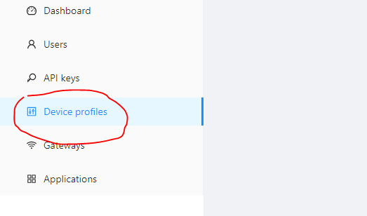
ChirpStack dashboard.
3. Click on the “Add device profile.”

The “Add device profile” in ChirpStack.
4. Fill out the general details as per the image below and then click “Submit.”

The LoRa general profile information on ChirpStack.
5. Turn off the OTAA because the device will run in ABP mode. Fill out all of the RX3 data rate details and frequency.

Selecting ABP mode and fill out the RX3 data rate details.
6. Turn on the Class-C mode as shown below and click “Submit.”

Enable Class C.
7. Add the “Application,” which contains all of the devices for it.

The “Applications” contain all of the devices.
8. Click on “Add application.”

Click on “Add application.”
9. Fill out the details of the Application as given below.

The “Application” details.
11. Next, click on the “Add device” button. This must be done anytime a new device is added.

Click on the “Add device” button.
12. Fill out the details as shown in image below. You’ll note, there is no Device EUI. We’ll learn how to find it in the next step.

The “Add device” profile but without the EUI.
How to find the keys and the EUI
1. To find the keys, open the serial port where Arduino Nano is connected, and press the “Reset” button.

The EUI details and keys information in serial.
LoRa data decoding
Open the LoRa application, which was recently added. Click on the “Events” tab to see the data.
When Parking Is EMPTY
When the distance of the sensor is greater than 10cm, then it sends the message, “Empty,” on the LoRa gateway.
When there’s an empty parking lot, the distance is greater than 10cm from the sensor.
An empty parking lot when distance is greater than 10cm from the sensor.
The data is represented in a hexadecimal value. You can go to any hexadecimal to text converter website and paste this data.
The hex data conversion shown as “EMPTY.”
When the distance is less than 10cm, then it sends the message, “Empty” on the LoRa gateway.

When there’s an occupied parking lot, the distance is greater than 10cm from the sensor.

The hex code as occupied parking
The data is once again represented in a hexadecimal value. You can go to any hexadecimal to text converter website and paste this data.

The hex data coverrsion as “OOCUPIED.”
Algorithm

The complete algorithm of the LoRa application for a smart cities parking sensor.
Code explanation
Arduino Nano
1. In this code section, the ultrasonic sensor emits a sound wave by setting the Trig pin to a high state. The sensor then receives the echo of this sound wave via the echo pin. By measuring the time taken for the echo to be received, the code calculates the distance between the sensor and the object reflecting the sound wave.

Snapshot of the code that measures the distance between the sensor and an object reflecting the sound wave.
2. This part of the code detects the condition of the parking area and sends it to LoRa device.

A snapshot of the code detects the condition of the parking area.
LoRa E5 Mini Board
1. Open lora_app.c file, which contains all of the code.

The main code file.
2. The CMD_GetChar function reads the characters available on the UART, and when it receives ‘\n’, it calls the CMD_process, which is sent LoRa.

Receiving data from the UART.
3. This function transfers the characters that are received to the app data buffer. It will not store the ‘\n’ or ‘\r’. Then, it sends it to the LoRa gateway.

The LoRa “Send” function process.
Multi-node communication
After successfully integrating one parking sensor with LoRa, the same setup and circuit can be easily replicated for another node. Each node is uniquely identified using the STM32 Device ID, ensuring that it acts as a different device with its own ID and keys.
This unique identification allows the new node to operate independently and communicate with the gateway as a separate device.
By using the STM32 Device ID, developers can avoid conflicts and ensure smooth communication between multiple nodes and the gateway. Each node’s unique ID enables precise tracking and monitoring of individual parking spaces or other applications.
This method’s ability to grow makes it ideal for setting up several nodes in different IoT projects. Whether it’s for smart parking, sensing the environment, or tracking assets, you can easily add new nodes to the network, making the whole system work together and collect more data.
You may also like:


Filed Under: IoT applications, Sensors, Tutorials

Questions related to this article?
👉Ask and discuss on EDAboard.com and Electro-Tech-Online.com forums.
Tell Us What You Think!!
You must be logged in to post a comment.