Monitoring temperature and humidity levels in real-time is essential for various manufacturing processes, as well as for applications in home automation and weather stations. A significant portion of FMCG products requires precise temperature and humidity control to maintain their quality.
To achieve accurate control, it’s necessary first to monitor these parameters, meaning they must be sensed, measured, and displayed.
Overview of Temperature and Humidity Monitoring with Graphics
In this tutorial, you’ll learn how to build a dynamic and interactive display using a TFT screen. It will not only display temperature and humidity readings from sensors like the DHT11 or DHT22 but also bring them to life with intuitive graphics and smooth animations using an Arduino. This guide will walk you through setting up the hardware, coding the interface, and enhancing your UI with animated visuals to create a sleek and responsive monitoring system.
Additional tutorials
Here are some other tutorials in this series on TFT screen displays worth reviewing:
- Sensor value display on TFT LCD using Arduino: Part I
- How to display sensor values on a TFT LCD using Arduino: Part II
- Sensor value (data) display on TFT LCD using Arduino – Part III
Real-life applications
There are many industries where temperature and humidity monitoring are critical:
- In the pharmaceutical industry, temperature and humidity are continuously monitored at every stage of medicine production to ensure accurate and consistent results.
- In the chemical industry, precise monitoring and control of temperature and humidity are crucial during the mixing and synthesis of chemical compounds.
- In the processed and packaged food industries, maintaining proper temperature and humidity is crucial for producing high-quality food products.
- In textile manufacturing, temperature and humidity monitoring improves fabric quality and color consistency.
- In greenhouse farming, plant health and growth depend directly on maintaining ideal temperature and humidity levels within the enclosure.
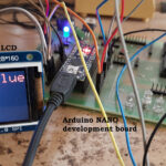
This project demonstrates how to monitor temperature and humidity using a 4.3-inch TFT LCD screen with multi-color graphics and animations, providing a more advanced and visually engaging interface compared to standard 7-segment displays or basic monochrome text LCDs.

Image 1. A prototype displaying real-time temperature and humidity on a TFT screen with an animated multi-color bar graph.
As shown in the above image, the TFT screen displays temperature and humidity using multi-color graphics and a color-changing animated bar graph. It also shows the maximum and minimum recorded values, providing a clear view of the variation range for both parameters. This approach offers a new and innovative method of monitoring temperature and humidity through engaging visuals and animation.
The project employs a DHT11 digital temperature and humidity sensor module paired with an Arduino Nano board. It also features a 4.3-inch SPI TFT LCD with a resolution of 480 x 320 pixels.
Components Required for Arduino TFT Temperature and Humidity Project
1. The DHT11 sensor module.

Image 2. The DHT11 sensor.
2. Arduino NANO

Image 3. The Arduino NANO board.
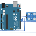
3. Arduino UNO

Image 4. The Arduino NANO board.
4. 4.3” SPI TFT LCD (480×320 resolution)

Image 5. A 4.3” SPI TFTLCD.
Circuit Diagram for Arduino Temperature and Humidity Monitoring

Image 6. The circuit connections between the TFT screen and Arduino UNO.
As shown in the above image, the circuit comprises only four components: the Arduino Nano board, the TFT display, the DHT11 sensor, and a few resistors used as a voltage divider network.
The interconnections are as follows:
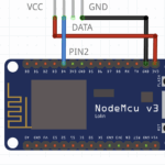
1. The DHT11 sensor module has three interface pins: (1) Vcc, (2) GND, and (3) Out. The Vcc pin is connected to Arduino’s 5-V output pin, and the Gnd pin is connected to the common circuit ground. The sensor output pin is connected to Arduino’s digital pin D3.
2. The TFT LCD has nine interface pins. These pins are connected to Arduino as specified in the table.

3. A voltage divider network (built using 1 and 2.2-K resistors) is placed between Arduino and the TFT LCD pins. This is necessary because the TFT LCD operates at 3.3 V, while Arduino outputs 5 V on its digital pins. The voltage divider converts the 5-V signals from Arduino to a safe 3.3-V level for the TFT LCD.
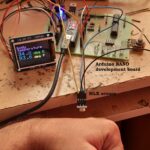
Below is a snapshot of the circuit and component arrangement.

Image 7. A complete prototype showcasing the temperature and humidity measurement on the TFT
screen with graphics.
Working Principle of Arduino Temperature and Humidity Monitoring System
The operation of the circuit can be summarized in one sentence: it displays the current room temperature and humidity on a TFT display.
Let’s look at how it works in detail:
- The DHT11 is a smart sensor that outputs digital values for temperature and humidity. It uses a one-wire protocol and provides direct digital data that the Arduino board can read.
- The Arduino reads output data from the DHT11 sensor every two seconds.
- It displays the current temperature in degrees Celsius (°C) and relative humidity in percent (% RH) on the TFT screen.
- The Arduino also tracks increases in temperature and humidity. Whenever either value increases beyond its previous maximum, the new maximum is updated and displayed on the screen.
- Similarly, if the temperature or humidity drops below the previously recorded minimum, the new minimum value is updated on the display.
- The display includes animated bar graphs for both temperature and humidity, with a color-changing feature. The bar fills or empties depending on whether the values increase or decrease.
- When the temperature rises above 41° C, the temperature bar changes color from green to red. Likewise, if humidity exceeds 90%, the humidity bar changes color from cyan to blue.
- This allows the temperature and humidity to be visualized clearly on a large 4.3-inch TFT display, using larger digits, multi-color graphics, and smooth animations.
Software program and logic
The operation of the circuit is controlled by a software program stored in the internal flash memory of the Arduino board’s microcontroller (ATmega328). The program is written in Arduino C/C++ and is compiled and built using the Arduino IDE. Once compiled, it is uploaded into the flash memory of the ATmega328.
The program uses the following three libraries:
- DHT11.h – Used to read data from the DHT11 sensor.
- LCDWIKI_GUI.h – Provides functions for displaying characters, numbers, shapes, animations, and creating a graphical user interface (GUI) on the TFT display.
- LCDWIKI_SPI.h – Handles communication between the Arduino and the SPI-based TFT display using the 4-wire SPI protocol.
Video
You may also like:


Filed Under: Electronic Projects, Video
Log in to leave a comment:
Lost your password?
Don't have an account? Register here