The Raspberrypi is a mini-computer board which is powerful enough to run large operating systems like Linux, Mac and Windows. The Raspberrypi is called a mini-computer because the SoC has the powerful ARM11 processor which runs on 700 MHz at its core and having the peripherals like timers, interrupt controller, GPIO, PCM / I2S, DMA controller, I2C, SPI slave, PWM, UART, USB, graphical processing unit (GPU) which includes VideoCore, MPEG-2 and MPEG-4 and a 512 MB SDRAM.
Linux operating systems especially Ubuntu is preferred for all kind of programming and development. The Raspberrypi is a board actually designed for helping computer education for remote schools but it is a nice platform for programmers especially beginners to explore various coding techniques. The immediate advantage of having an Operating System like Ubuntu running on an embedded system device is multitasking.
In a multi-tasking environment of the Operating System several processes executes at the same time and the Signals provide an Inter-Process Communication (IPC) method. The Operating System sends signals to the process to notify them about the events occurred and to control them. A Parent process can create another process, which are called the Child process and the Parent process can use signals to control the Child process. This project demonstrates the implementation of a Process system which is controlled by a Parent process using signals.
In this project the Raspberrypi board is loaded with Ubuntu and is remotely accessed using VNC. The Raspberrypi board is also connected to the internet. There are 26 connectors which can be taken out from the connector port of the Raspberrypi board. All the connector pins are taken out using 13*2 pin female connectors and at the other end of their wire 26 pin Burg stick male connectors are attached. The Burg stick male connectors allow each pin out from the Raspberrypi board to be plugged into the holes of a breadboard. To access the pins that coming out of the Broadcom controller of the Raspberrypi board using C language, a C library is available called “bcm2835” which has been downloaded and installed.
A signal is sent for the purpose of notifying the process about something that required immediate attention. Different signals are used to notify different events and the signals are differentiated by their signal numbers. The list of all the available signals in the OS and their signal numbers can be obtained using the following command:
kill -l
The following table gives a list of the most common signals that a process might encounter in an Operating System:
|
NAME |
NUMBER |
DESCRIPTION |
|
SIGHUP |
1 |
Linux sends a process this signal when it becomes disconnected from a terminal. |
|
SIGINT |
2 |
Linux sends a process this signal when the user tries to end it by pressing CTRL+C. |
|
SIGILL |
4 |
Linux sends a process this signal when it attempts to execute an illegal instruction. |
|
SIGABRT |
6 |
Linux sends a process this signal to the process when the process calls the ‘abort ()’ function |
|
SIGFPE |
8 |
Linux sends a process this signal when it has executed an invalid floating-point math instruction |
|
SIGKILL |
9 |
Linux sends a process this signal to end it immediately |
|
SIGUSR1 |
10 |
User programs can send this signal to other process |
|
SIGUSR2 |
12 |
User programs can send this signal to other process |
|
SIGSEGV |
11 |
Linux sends a process this signal when the program has attempted an invalid memory access |
|
SIGPIPE |
13 |
Linux sends a process this signal when the program has attempted to access a broken data stream, such as a socket connection that has been already closed |
|
SIGALRM |
14 |
A process can receive this signal from the Linux using the function alarm(), after a time period mentioned in its argument. |
|
SIGTERM |
15 |
Linux sends a process this signal requesting it to terminate |
|
SIGCHLD |
17 |
Linux sends a process this signal when a child process exits |
|
SIGXCPU |
24 |
Linux sends a process this signal when it exceeds the limit of CPU time that it can consume. |
|
SIGVTALRM |
26 |
A process can receive this signal from the Linux using the function setitimer (), after a time period mentioned in its argument. |
Fig. 2: List of common signals for Interprocess Signalling in Operating System
In this project a Parent process creates so many Child process and controls them using the signal 12 which is the ‘SIGUSR2’. The two signals ‘SIGUSR1’ and the ‘SIGUSR2’ are reserved for the user applications and hence they can be used in this project also.
In this particular project a Parent creates 8 Childs process which are then used to control 8 LEDs connected to the IO pins of the Raspberrypi board. The Child processes are then made to change the glowing state of the LED by sending ‘SIGUSR2’ signal. This forms a Process System made up of several Child process and a Parent process and the entire system is controlled by the Parent process. The diagrammatic representation of the Process System is given below:
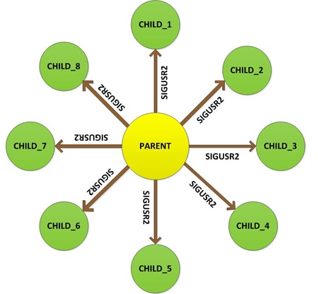
Fig. 3: Block Diagram of Interprocess Signalling in Raspberry pi
The Parent process creates the Child processes using the fork () function. The fork is a function which takes no argument but has two return values. When the Parent calls the fork (), it always returns a positive value on success. The positive value which the Parent receives is the process-id of the newly created Child process. The Child process however get a value ‘0’ from the same fork () function call.
Thus the Parent can store the process-id of each and every Child process that has been created. Using this process-id the Parent process can send a signal to a particular Child process with the help of the function ‘kill ()’. The ‘kill ()’ is the function that can be used to send any signal to any process and more details are discussed in the following section:
kill ()
The kill () is a function defined in the header file <sys/signal.h> which can be used to send a specified signal to a specified process. The prototype of the kill () function is given below;
int kill ( pid_t pid, int sig );
The first argument asks for the process-id of the process to which the Signal needs to be sent. The second argument is the Signal number that needs to be sent to the specified process. If kill () fails to send a signal, it returns a value of -1.
In each of the Child Process there is a Signal Handler which can handle the ‘SIGUSR2’ signal. In this particular project whenever the Child receives the ‘SIGUSR2’ signal their Signal Handler will change the state of an associated output pin every time.
***Note that in this project the latest version of library “bcm2835” is used with an old version of Raspberrypi board. It is not possible to access the pin number 13 of the old board with the latest library version and hence in the pin number 24 is used to blink the 3rd LED. The circuit diagram is also drawn accordingly. Those who have the latest version of the board can use the pin 13 without any trouble.
To find the ‘Revision’ and other important details about the Raspberrypi board, use the following command:
cat /proc/cpuinfo
Project Source Code
###
#include <bcm2835.h>#include <pthread.h>#include <unistd.h>#include <signal.h>#define PIN1 RPI_GPIO_P1_11#define PIN2 RPI_GPIO_P1_12#define PIN3 RPI_GPIO_P1_24#define PIN4 RPI_GPIO_P1_15#define PIN5 RPI_GPIO_P1_16#define PIN6 RPI_GPIO_P1_18#define PIN7 RPI_GPIO_P1_22#define PIN8 RPI_GPIO_P1_07void set_pins_output ( void );void set_all_pin_low ( void );void toggle1_on_signal_rx ( void );void toggle2_on_signal_rx ( void );void toggle3_on_signal_rx ( void );void toggle4_on_signal_rx ( void );void toggle5_on_signal_rx ( void );void toggle6_on_signal_rx ( void );void toggle7_on_signal_rx ( void );void toggle8_on_signal_rx ( void );void toggle1_sig_handler ( int signo );void toggle2_sig_handler ( int signo );void toggle3_sig_handler ( int signo );void toggle4_sig_handler ( int signo );void toggle5_sig_handler ( int signo );void toggle6_sig_handler ( int signo );void toggle7_sig_handler ( int signo );void toggle8_sig_handler ( int signo );pid_t child_id [ 8 ];int main ( void ){int i;if (!bcm2835_init())return 1;set_pins_output ();set_all_pin_low ();if ( ! ( child_id [ 0 ] = fork () ) ){toggle1_on_signal_rx ();_exit ( 0 );}else;if ( ! ( child_id [ 1 ] = fork () ) ){toggle2_on_signal_rx ();_exit ( 0 );}else;if ( ! ( child_id [ 2 ] = fork () ) ){toggle3_on_signal_rx ();_exit ( 0 );}else;if ( ! ( child_id [ 3 ] = fork () ) ){toggle4_on_signal_rx ();_exit ( 0 );}else;if ( ! ( child_id [ 4 ] = fork () ) ){toggle5_on_signal_rx ();_exit ( 0 );}else;if ( ! ( child_id [ 5 ] = fork () ) ){toggle6_on_signal_rx ();_exit ( 0 );}else;if ( ! ( child_id [ 6 ] = fork () ) ){toggle7_on_signal_rx ();_exit ( 0 );}else;if ( ! ( child_id [ 7 ] = fork () ) ){toggle8_on_signal_rx ();_exit ( 0 );}else;bcm2835_delay( 1000 );while ( 1 ){for ( i = 0; i < 8; i ++ ){bcm2835_delay( 500 );kill ( child_id [ i ], SIGUSR2 );}}bcm2835_close();return 0;}void set_all_pin_low ( void ){bcm2835_gpio_write(PIN1, LOW);bcm2835_gpio_write(PIN2, LOW);bcm2835_gpio_write(PIN3, LOW);bcm2835_gpio_write(PIN4, LOW);bcm2835_gpio_write(PIN5, LOW);bcm2835_gpio_write(PIN6, LOW);bcm2835_gpio_write(PIN7, LOW);bcm2835_gpio_write(PIN8, LOW);}void set_pins_output ( void ){bcm2835_gpio_fsel(PIN1, BCM2835_GPIO_FSEL_OUTP);bcm2835_gpio_fsel(PIN2, BCM2835_GPIO_FSEL_OUTP);bcm2835_gpio_fsel(PIN3, BCM2835_GPIO_FSEL_OUTP);bcm2835_gpio_fsel(PIN4, BCM2835_GPIO_FSEL_OUTP);bcm2835_gpio_fsel(PIN5, BCM2835_GPIO_FSEL_OUTP);bcm2835_gpio_fsel(PIN6, BCM2835_GPIO_FSEL_OUTP);bcm2835_gpio_fsel(PIN7, BCM2835_GPIO_FSEL_OUTP);bcm2835_gpio_fsel(PIN8, BCM2835_GPIO_FSEL_OUTP);}void toggle1_on_signal_rx ( void ){signal ( SIGUSR2, toggle1_sig_handler );while ( 1 );}void toggle2_on_signal_rx ( void ){signal ( SIGUSR2, toggle2_sig_handler );while ( 1 );}void toggle3_on_signal_rx ( void ){signal ( SIGUSR2, toggle3_sig_handler );while ( 1 );}void toggle4_on_signal_rx ( void ){signal ( SIGUSR2, toggle4_sig_handler );while ( 1 );}void toggle5_on_signal_rx ( void ){signal ( SIGUSR2, toggle5_sig_handler );while ( 1 );}void toggle6_on_signal_rx ( void ){signal ( SIGUSR2, toggle6_sig_handler );while ( 1 );}void toggle7_on_signal_rx ( void ){signal ( SIGUSR2, toggle7_sig_handler );while ( 1 );}void toggle8_on_signal_rx ( void ){signal ( SIGUSR2, toggle8_sig_handler );while ( 1 );}void toggle1_sig_handler ( int signo ){static int state = 0;state = ~state;bcm2835_gpio_write ( PIN1, state );}void toggle2_sig_handler ( int signo ){static int state = 0;state = ~state;bcm2835_gpio_write ( PIN2, state );}void toggle3_sig_handler ( int signo ){static int state = 0;state = ~state;bcm2835_gpio_write ( PIN3, state );}void toggle4_sig_handler ( int signo ){static int state = 0;state = ~state;bcm2835_gpio_write ( PIN4, state );}void toggle5_sig_handler ( int signo ){static int state = 0;state = ~state;bcm2835_gpio_write ( PIN5, state );}void toggle6_sig_handler ( int signo ){static int state = 0;state = ~state;bcm2835_gpio_write ( PIN6, state );}void toggle7_sig_handler ( int signo ){static int state = 0;state = ~state;bcm2835_gpio_write ( PIN7, state );}void toggle8_sig_handler ( int signo ){static int state = 0;state = ~state;bcm2835_gpio_write ( PIN8, state );}###
Circuit Diagrams
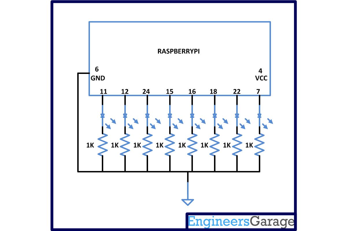
Project Components
Project Video
Filed Under: Raspberry pi
Filed Under: Raspberry pi
Log in to leave a comment:
Lost your password?
Don't have an account? Register here