[[wysiwyg_imageupload:1976:]]This Project report is contributed by S. Sridevi from ARULMIGU MEENAKSHI AMMAN COLLEGE OF ENGINEERING, VADAMAVANDAL.
1. INDUSTRIAL PROFILE
1.1 INTEGRAL COACH FACTORY
The integral coach factory is a production unit of the Indian railways was set-up under the first five-year plan.ICF is started with the transfer of coach building technologies from m/s SWISS CARS AND ELEVATORS, Manufacturing Corporation, Switzerland.
The prime minister of India inaugurated the production unit Shri. Pandit Jawaharlal Nehru on 2nd October, 1955.
ICF has evolved for over 300 designs consist of
· sleeper coaches
· Air conditioned coaches
· Self propelled coaches
· Diesel and mainline electric multiple units (EMU, DMU, MEMU)
· Metro coaches
· Diesel Electric Tower Cars (DETC)
· Accident Relief Medical Vans (ARMV)
· Inspection Cars (RA)
· Fuel Test Cars
· Track Recording Cars
· The latest coaches are for the Deccan Odyssey (a luxury train of the Indian Railways)
· coaches for MRVC (world class coaches)
· ICF business span covers design, development and manufactures of varies types of coaches for Indian railway and for export.
1.2 SALIENT FEATURES OF ICF COACHES:
· All steel welded body
· Anti-telescopic structure
· Good riding quality
· Light weight
· High speed
· Adopting corrosion prevention method
· Safe and economical design
· Improved amenities
· Fine proof measure
1.2 DEPARTMENTS IN ICF:
· Mechanical
· Electrical
· Engineering
· Personnel
· Security
· Accounts
· Stores
· Medical
CHAPTER 2- INTRODUCTION
The main aim of our project is to ensure safety on the track and to avoid ‘parting’ to a larger extent.Most, if not all railways deploy safety systems, mainly to prevent trains from crashing into each other.
At the implementation level, on considering the former one, our safety system is based on the principle that trains cannot collide if they are not permitted to occupy the same section of track at the same time. Therefore, the railway lines are divided into blocks where a detection system detects the present condition of a train and sets signals at the entrance of the block accordingly to it.
On considering the later one, even though parting is a momentary phenomenon; it mostly occurs in ductile materials, where ductile materials take a long time to lose their tensile strength and breakup finally.
The implementation of the topic must be possible at running condition also.For that purpose a detailed study of certain real time traction systems and various parts involved in is necessary.Therefore, before going into our topic, let us take a brief view about the control elements involved in our topic for efficient practical implementation.
2.1 STUDY OF ESSENTIAL REAL TIME COMPONENTS
2.1.1 Traction Motors:-
The project consists of two circuit diagrams among them one contains a circuit to control engine motor i.e… Traction motor.Therefore, the ratings of various traction drives and their types are given below.
Only three types of traction motors are manufactured in ICF.
They are
· DC Series Traction Motor for AC EMU
· DC Series Traction Motor for DEMU
· AC/DC series Traction Motor for World Class Coaches.(MRVC units)
Among the above, three types only first two are commonly used in Indian railways.
RATING OF DC SERIES TRACTION MOTOR FOR AC EMU:
· 535V, 340A, 167KW (continuous rating).
· 535V, 350A, 187KW (1hr rating).
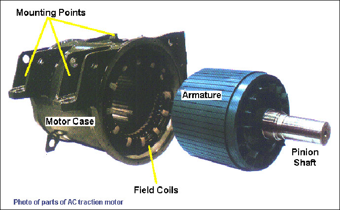
Fig 2.1.1AC Traction Motor
RATING OF DC SERIES TRACTION MOTOR FOR DEMU:
· 1160 rpm, 557V, 415A, 208KW(continuous rating)
· 1115rpm, 557V, 457A,208KW(1hr rating)
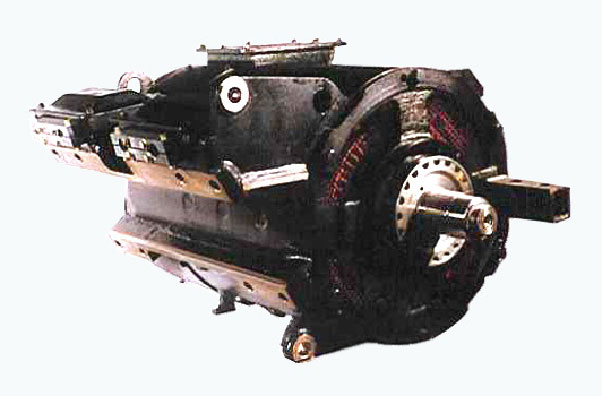
Fig 2.1.2DC Series Traction Motor For DEMU
RATINGS OF AC/DC MULTIPLE UNIT FOR WCC
Three phase VVVF controlled asynchronous squirrel cage induction motor, 6 pole, 250KW, 162A, 1029V, 1259rpm, 0.81pf, 64Hz.
2.1.2 Need For Control Description:
The project handles the complication of braking and control of engine DC motor on performing the operations like forward motion, reverse motion, speed control and stop during integrity checking and parting.For performing those operation efficiently ,a brief description about the controller section is given below.
2.1.3 Master Controller:
Here master- slave control technique is used between DC MEUs where communication in two way is possible but command passes only from master control motor to slave The commands for driving and direction selection are issued from the motor controllers. It consist of following components
1. Direction selection switch
· Forward(F)
· Neutral(N)/ Coasting
· Reverse(R)
2. Traction/ brake controller
It is used for distributing the traction /brake controller torque request from the drive to train.
3. Dead-man switch
It is incorporated in the traction /brake controller. To activate the dead-man through the handle, the driver must turn it by approximately 5degree when the mode selector is in forward or reverse position then only a driver is able to power the train.
2.1.4 Control Drive/Brake Reference:
The train is stopped two or three times during parting rectification process.So, proper knowledge about the braking system, its types and utilisation of multiple braking methods in traction drives is needed f or real time implementation. They are given in a detailed manner as below. To understand the drive/brake control of the train it is necessary to know that there are five different operations executed at five different working conditions or modes.They are,
· Emergency braking
· Normal braking
· Automatic braking
· Coasting
· Driving
EMERGENCY BRAKING:
The brake pipe is discharged and full pneumatic is applied. The operation mode is reached when the driver puts the traction/brake controller in ‘EB’ position releases the dead man, switches the mode selector in neutral position or put the brake controller in emergency or brake position.
NORMAL BRAKING:
The EP/ED brakes are used to brake the train. The braking of the train is controlled by BECU (Brake Electronic Control Unit).There are two types of brake cylinder pressure sensor is provided one for BECU and TCU. The brake pipe stays charged and the automatic brake is not applied. To reach this mode, the traction/brake controller must be in the braking position.
UTOMATIC BRAKING:
Automatic braking is used when the deceleration, using EP and ED brakes, is not sufficient. They are used in the case one or more vehicles in the train are not capable of braking through EP and ED brakes.
COASTING:
Here no drive or brake force is applied. To reach this mode, the traction/brake controller must be in coasting position.
2.1.5 Brake Equipments:
These equipments used mainly for braking operation. For all the four above-mentioned braking methods totally two valves, three brakes and a compressor is used.They are listed below.
1. Driver’s brake valve
2. Emergency brake valve
3. Electro pneumatic brake
4. Pneumatic brake
5. Parking brake
6. Compressor
415VAC, 50HZ, 6.7KW, 12.7A
Working pressure: 10bar
Weight: 180
2.1.6 Drivers’ Cab Equipments:
For controlling either traction or prototype motor actual replication of a driver’s cabin is necessary.The second circuit diagram mentioned in the project is the actual miniature of a drivers’ cabin.The various equipments present in a driver cabin
· Master controller
· Direction selection switch
· Brake controller , Dead-man switch
· LED indication panel
· Ecab for a control and auxiliary MCB’s
· Train ON-OFF driver control switch.
2.1.7 NEED FOR STUDY OF COUPLERS:
For taking necessary actions during ‘Parting’ or ‘Decoupling’ detailed information about the type,nature of the material used and the construction of the couplings and individual coupler needed. A detailed information information regarding the couplings used in Indian Railways are given below.
2.1.7 COUPLERS
A coupling (or a coupler) is a mechanism for connecting rolling stock in a train. The design of the coupler is standard, and is almost as important as the railway gauge, since flexibility and convenience are maximised if all rolling stock were coupled along with it.
In order for two railway vehicles to be connected, together in a train they are provided with couplers. Since there are a large number of railway vehicles, which might have to be coupled at one time, or another in their lives, it would seem sensible to ensure that the couplers are compatible and are at a standard position on each end of each vehicle.
Integral coach factory manufactures only four types of couplers for carriages and locomotives in India. They are
1) IRS couplers
2) CBC –Centre Buffer Coupler
3) ABC-Auto Buffer Coupler
4) Schaku coupler
Among the four only three types are used now. The auto buffer couplers are not manufactured now a days due to its various difficulties. Let us have a detailed view on other types.
BAR COUPLER:
The simplest type of coupler is a link and pin. Each vehicle has a bar attached to the centre of the headstock which has a loop with a centre hole attached to it. Each coupler has a bellmouth around the end of the bar to assist in guiding the bar with the hole into place. The loops are lined up and a pin dropped into them. 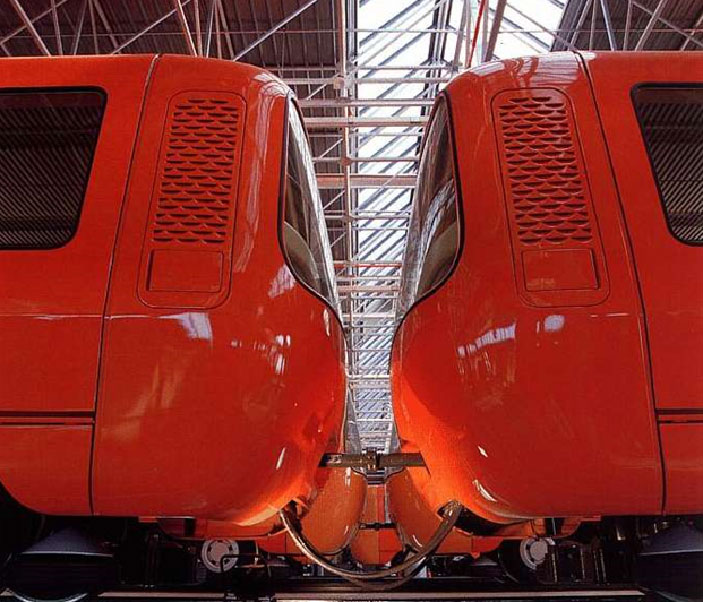
Fig.2.1.7(a) Bar coupler
The common type of coupler is the bar coupler. This is also known as a semi permanent coupler. It cannot be disconnected unless the train is in a workshop and access underneath the train is available. It is normally used in EMUs, which are kept in fixed formations of two, three or four cars. The bar couplers are located within the unit, while the outer ends of the unit have some type of easily disconnected coupler. Bar couplers are simple, just consisting of a bar with a hole at the inner ends through which the car body is connected by a bolt. Others consist of two halves, which are bolted together.
IRS OR 3-LINK COUPLING:
This type of coupling is exactly what it says – a set of three links, which are hanging from hooks on each vehicle. A development of this is the “Instanter” coupler, which has a middle link forged into a triangular shape to allow the distance between vehicles to be adjusted. This is to allow the side buffers used with the coupler to be adjacent to each other and provide some degree of slack cushioning.
The coupler required a person to get down on the track between the two vehicles and lift the coupling chain over the hook of the other vehicle. Sometimes a “coupling pole” was used for quickly uncoupling freight wagons.
This is a development of the same coupling where the middle link is replaced by a screw. The screw is used to tighten the coupling between the two vehicles to provide for cushioning by compressing the side buffers. The following photos show typical screw couplings.
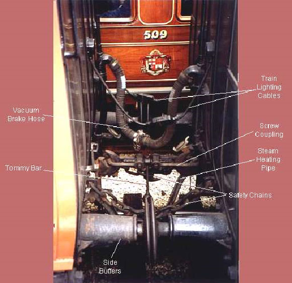 Fig 2.1.7(b) IRS COUPLING
The photo above shows a coupled screw coupler also showing typical fittings of passenger vehicle coupling In addition to the mechanical couplings required connecting the vehicles; trains had to have through connections for brakes, lighting and heating. In this photo, the arrangements for coupling two passenger coaches in a steam hauled train are shown. This particular type of coach is provided with safety chains, which are fitted in case the main coupling broke.All the work involved in connecting the two vehicles is carried out manually. They involve hard work and sometimes dangerous.
CBC –CENTRAL BUFFER COUPLER:
It is also known as buckeye or knuckle coupler or alliance coupler.
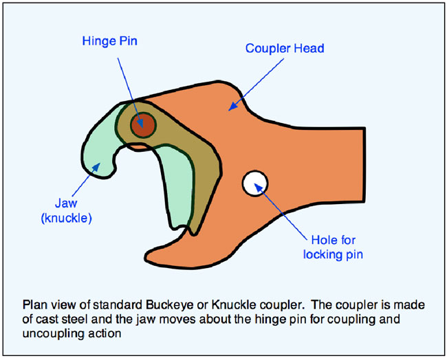 Fig 2.1.7(c) CBC coupler-plan view
By far the most common coupler seen around the world is known variously as the “Knuckle”, “Buckeye” or “Janney” coupler, diagram left. This is an automatic, mechanical coupler of a design originating in the US and commonly used in other countries for both freight and passenger vehicles. The term “Buckeye” comes from the nickname of the US state of Ohio “the Buckeye state” which originally marketed the coupler. Link and pin coupler required staff to stand between cars to couple and uncouple and there were many injuries and even deaths as a result.
The coupler is made of cast steel and consists of four main parts. The head itself, the jaw or knuckle, the hinge pin, about which the knuckle rotates during the coupling or uncoupling process and a locking pin. The locking pin is lifted to release the knuckle. It does this by raising a steel block inside the coupler head which frees the knuckle and allows it to rotate. The simplified diagram below shows the steps when two couplers are being coupled.
 Fig 2.1.7(d) Top View Of CBC Couplers
To couple two vehicles, the knuckles must be open. When the two vehicles are pushed together, the knuckles of the two couplers close on each other and are locked from behind by a vertical pin dropping a steel block into place behind a raised casting on the knuckle. To uncouple, one of the pins must be pulled up to release the block locking the knuckle. This is done by operating a lever or chain from the side of the vehicle. 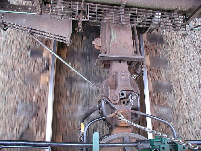
Fig 2.1.7(d) Standard CBC Type E Couplers performing their function in Freight Train
SCHAKU COUPLERS OR SCHARFENBERG AUTOMATIC COUPLER:
More and more railways are using scharfenberg automatic couplers. A fully automatic coupler connects the vehicles mechanically, electrically and pneumatically, normally by pushing the two vehicles together and then operating a button or foot pedal in the cab to complete the operation. Uncoupling is done by another button or pedal to disconnect the electrical contact and pneumatic connection and disengaging the coupler mechanically.
Fully automatic couplers are complex and need a lot of maintenance care and attention. They need to be used often to keep them in good working order. There are a number of different designs in use. 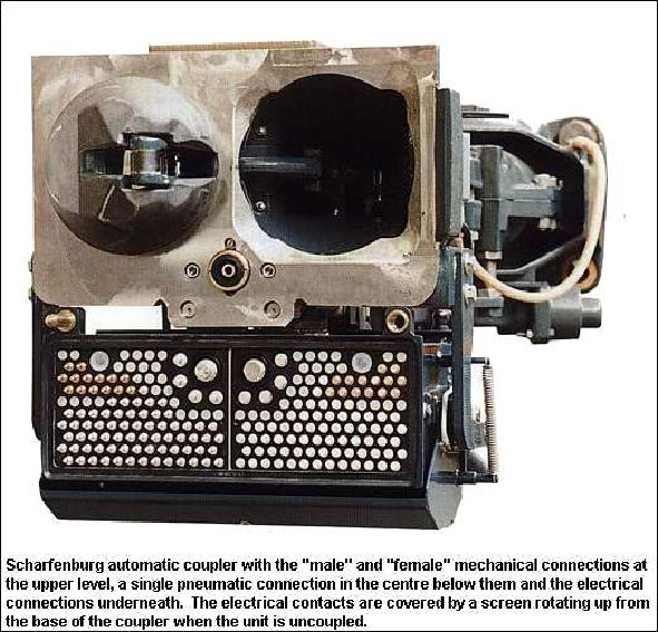
Fig 2.1.7(e) Auto
COUPLING MECHANISM
It consists of two mechanical projections in it. One is cone, other is funnel.The cone, funnel shape of the coupler front face profile ensures a generous gathering range both horizontally and vertically and allows automatic coupling on curves, even with vertical mismatch and very low speed.
Minimal force is only required for successful coupling. The coupler faces and the locking system form a rigid connection both vertically and horizontally. The parallelogram arrangement of the coupler locks provides uniform distribution of the draft load. This coupler lock design ensures minimal wear and maximum coupler longevity. The rigid and slack-free connection enables jerk free acceleration and braking and offers optimum ride comfort. It also prevents the cars overriding in the case of an accident.
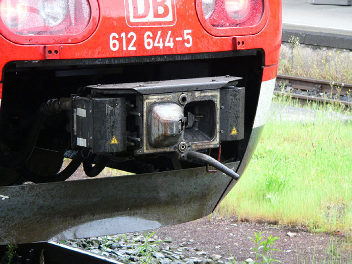
Fig 2.1.7(f) Schaku in Train Carrsiage
2.2EXISTING SYSTEMS:
The project is a primarily designed as a solution for overcoming the defaults in the existing methods to check integrity.The current method of track based sensing has got many difficulties in it.The working principle and the difficulties were discussed in a detailed manner.
2.2.1 Track based sensing method:
Detecting a train in a segment is done by measuring the current flowing from one rail through the train’s axles to the other rail that means the train effectively short circuits the rails or by counting the number of axles driving into and out of the segment. To prevent a train from entering an occupied segment, the system provides means to control the movement of the train. It is able to stop or slow down a train when it is about to pass over a red signal.
Control information is transmitted to the train by antennae on the track or by signals sent through the rails. The current situation has many drawbacks. The most obvious one is that there is no standardization throughout India. Trains crossing borders must be equipped with all applicable systems.
2.2.2 Defaults in track based sensing:
Train safety is infrastructure based and because of the amount of trackside equipment, maintenance is labour intensive and expensive. Under normal conditions only one train is allowed in a segment because the length of a segment is fixed that ranges from one to several kilometers the gap between trains is often much wider than needed, resulting in poor track utilization.
Tracks could be used much more efficiently if the distance between trains would be flexible and based on length, weight and speed of the trains.?
Sometimes a carriage is accidentally decoupled from the train. The train must be checked to see whether all carriages are still present. In the old system, this was done in the trackside system by counting axels. For passenger trains this is not very difficult to realize, as there are many mechanical and electrical connections between the carriages.
In contrast to passenger trains, carriages in cargo trains are only mechanically connected with chains and hooks, and compressed air lines for the brakes.
2.2.3 Solution:
The only solution to eliminate the above-mentioned defaults in using train based wireless sensor network instead of track based sensor systems.
2.3REQUIREMENTS:
An integrity safety system should meet a number of requirements for effective funtioning of the system.
2.3.1 Functional Requirements
· Coupling and uncoupling with integrity system must not take more time or involve more actions than without integrity system.?
· The integrity system must require human intervention as little as possible, reducing the risk of human errors.
· The engine driver must be presented a clear state of the train’s integrity.
2.3.2 Hardware Requirements:
Wireless is preferred over wired. Connecting and disconnecting wires takes time and is error prone in the railway environment.
· The integrity system must not require radical changes to the design of cargo carriages. It must be a simple add-on that is installed once on existing carriages.
· There must be no operational degradation. The system may not wear out over time.
Hardware must be well suited for the harsh railway environment. It must be robust and shock proof.
2.3.3 List of Hardware components used:-
The list of components used for the project model is given below.
. LV-Masonry®-EZ1-High Performance Ultrasonic sensor.
. A pair of RF transmitter and receiver.
. RLP434A SAW based RF Receiver (433.92 Mhz).
. RF transmitter TLP434A (433.92Mhz)
. HT12E Encoder and HT12D Decoder where Encoder is used along with transmitter and decoder is used along with receiver.
. TwoAT89S52 microcontrollers.
. Two PMDC motors.
· One of the motors is for prototype control, which is the motor for the miniature of the train and other motor is for hook control.
For effective integrity sensing ,we are using USS in the WSN for its notable features.
2.3.4 FEATURES OF ULTRASONIC SENSOR
- The ultrasonic sensor that we are using is very sensitive, even small distance if 1mm deviation can be easily identified. The signal transmission is also very fast.
- Due to this, it is easy to take corrective measures now of risk.
- Whenever the effective distance changes, it first develops vibrations. If those vibrations exceed a certain range, the sensor will sense that also.
- Then the engine speed is adjusted to reduce stress over the coupling.
- Therefore, sensing and rectification before the moment of decoupling is possible.
2.4 CASE STUDIES:
2.4.1 Murulla rail accident 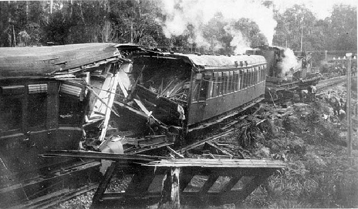
Fig 2.4.1 Damaged Carriage Picture
The Murulla rail accident involved the collision of the Sydney-bound Northwest Mail Train with runaway goods wagons near Murrurundi, New South Wales, in the Upper Hunter Valley on 13 September 1999. Nearly 26 persons lost their lives.
A goods train had become divided and the attempts of the train crew to re-unite the portions resulted in 12 vehicles running away down a steep gradient, and colliding with the approaching mail train.
This was the worst accident on the New South Wales rail network until the Granville railway disaster in 2005.
The signal box at Murulla controlled a loop line for trains to pass on a single line railway; there were no other connections at the location. Electric Train Staff operated between Wingen and Murulla and Electric Tablet operated between Murulla and Blandford.
Train no.62, southbound goods train comprised a standard goods engine hauling 34 wagons and a brake van were to pass through Murulla on the main line. Another goods train, no 95, working in the opposing direction, had entered the loop line and was waiting for no 62 to pass. No 62 had a length of 951 feet (290 m) and a load of 746 tons (758 t). All vehicles were fitted with Westinghouse air brake.
The train slowed at Murulla signal box for the exchange of the single line tokens, and as the train staff for the onward section was received, the driver of no.62 put on steam. The shock resulted in the train to become divided, with the rear twelve vehicles separating from the main train. This was later attributed to the failure of a draw hook. The driver noticed the division of the train and both portions of the train were safely brought to a stand.
Both portions of the train were verified to be within the clearance points of the loop line, so train no. 95 was permitted to depart.
The detached portion of no.62 consisted of 12 vehicles and its length 331 feet with a weight of 264 tons. Handbrakes were applied to these vehicles. It would appear that the train staff in the possession of the engine crew was returned to the instrument in the signal box at this time, and all vehicles were within the confines of the home signals.
After a number of attempts to fit a tail rope, the brake van had been shunted back, foul of the clearance point for the loop line. The two opposing vehicles at the separation were finally hitched with a single wire rope connection, but the airbrake hoses could not be connected. The signalman then requested that the train be brought forward so that it was clear of the clearance point to permit the approaching southbound no.8 Mail train to pass through the loop.
The guard of no.62 released the handbrakes on the rear portion, leaving it un-braked and the driver went forward to his engine. When he started the train the tail rope broke and the rear portion began to run back down the grade towards Bland ford, coming into collision with the approaching mail train just beyond the up distant signal. The collision resulted in the death of 26 persons.
2.5 BLOCK DIAGRAM-I(OVERALL BLOCK DIAGRAM) 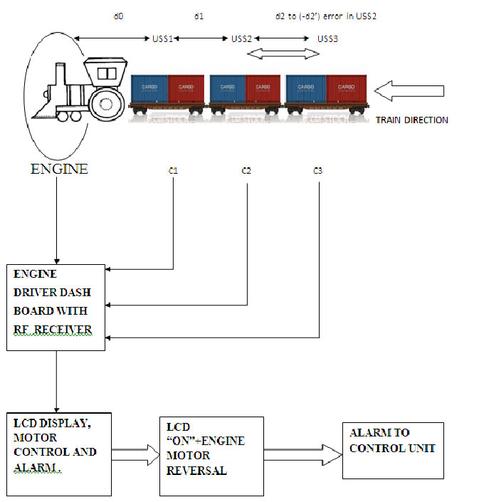
Fig 2.5 Overall Block Diagram
2.5.1 BLOCK DIAGRAM- I
EXPLANATION:
The ultrasonic sensors are placed in every carriages.Each USS is connected with a transmitter and the pairing receiver is placed in the engine driver dash board.
Every USS is placed at the end of carriage at a predefined distance.All transmitters are connected to a single receiver at the engine.
The receiver is connected to a microcontroller circuit with LCD display, alarm and engine motor control.
(a)LCD dislay for indicating the location of the carriage.
(b)Alarm is also present for purpose of indication.
(c)Engine control is mainly for performing four operations sequentially during parting.They are
STOP
REVERSE
STOP
FORWARD/ START AGAIN.
Whenever the effective distance between the sensor changes, USS senses it and it sends RF signal to the engine driver through the microcontroller circuit in the carriage.
Then the microcontroller in the engine driver dashboard sends “alert” signal to the driver for engine speed control.
All types of couplers used in train are ductile in nature.So prevention before parting or decoupling is possible by adjusting the speed of train engine.
So, parting is avoided upto this extent using the methods.Instead of all these measures parting happens means,the USS itself senses the couplings and send signals to activate the second circuit in carriage end which take necessary steps to eliminate the problems due to parting.
2.6 BLOCK DIAGRAM –II
2.6 ENGINE DRIVER DASH BAORD CIRCUIT:  Fig 2.6.1 Engine Driver Dash Board Block Diagram
Fig 2.6.1 Engine Driver Dash Board Block Diagram2.6.1 BLOCK DIAGRAM II-EXPLONATION
Whenever the carriages decoupled, USS senses and RF transmitter transmit a decoupled signal to RF receiver which is at engine driver dash board. The RF receiver decodes the signal and it given to microcontroller. Microcontroller gives control signal for motor unit to reverse the engine, also to alarm and LED display.
The current situation of a particular train is informed to control station at remote area through wireless transmitters.
CIRCUIT DIAGRAM I
MICROCONTROLLER CIRCUIT AT THE CARRIAGE END
2.7 CIRCUIT AT THE CARRIAGE END: Check Circuit D
2.7.1 Circuit diagram I consist of following sections:
1. Ultrasonic sensor with serial port transmitter and receiver
2. Microcontroller
3. Power supply
4. Encoder and transmitter section
5. Hook motor control relay
The ultrasonic sensor detects the distance between the two carriages. Whenever it detects decoupling through serial port transmitter and receiver to microcontroller, the microcontroller has coded program to perform there two operations simultaneously. They are
· The transmitter sends the signal at the rate of 433.49MHZ to the receiver at the engine side.
· The signal is given to the hook motor to raise the hook is given.
· Another signal to stop and reverse the engine motor through encoder is also given.
· After transmitting the signal to main engine to stop the train, the microcontroller has a prewritten program, which sends a command to the relay to switch “ON” the hook control motor for raising the hook upwards.
· The hook control motor has a tensile rope surrounding it on one end and other end tied to the hook.
· After raising the hook through the control motor, the encoder-transmitter set sends a signal to move the train backwards.
· Meanwhile, the ultrasonic sensor senses the distance between two carriages.
· Whenever the train reaches a specified distance, the sensor senses it and sends signals to microcontroller.
· There by it sends signal through transmitter to stop the train.
· After the “STOP” operation, a command from microcontroller is sent to switch OFF motor for re-coupling of hook by falling operation.
· Then a signal from transmitter will be sent to the main engine for forward motion of the train.
· If the hook is not coupled rightly, then the above operations are all repeated again until the re-coupling process is perfect.
CIRCUIT DIAGRAM II
MICROCONTROLER CIRCUIT AT THE ENGINE DRIVER DASH BOARD
2.8 CIRCUIT AT THE ENGINE DRIVER’S CABIN: Circuit has been explained in Circuit Diagram Tab2.
2.8.1 EXPLANATION FOR CIRCUIT DIAGRAM -II
Circuit diagram II consists of following sections
1. Receiver, decoder section
2. Microcontroller
3. LCD display
4. Motor control section
5. Power supply
Receiver, Decoder section:
The receiver signal at the frequency of 433.92MHz and rejects signal with other frequencies. The received frequency is reduced to 38 KHz in the receiver section itself. Then signal passes to the microcontroller.
· The microcontroller has a prewritten program to stop the engine during the detection of decoupling at carriages.
· Simultaneously the carriages number and distance between two carriages are displayed in LCD section.
· After receiving the signal from transmitter on raising the hook at carriage end, the engine direction is reversed on operating the relays S1, S2 to no change condition.
· The engine is reversed until it reaches a defined position (specified distance) between carriages.
· The reversing motion is stopped on receiving the signal from ultrasonic sensor to stop it.
· Then the engine starts moving on forward direction through relays S3, S4 on getting the confirmation signal of hook coupling at the end of the carriages.
3.CONCLUSION:
3.1FEATURES AND FUTURE PLANS
. Existing solutions to check train integrity are almost with exceptions based on trackside systems, while our solution exclusively depends on the train based WSN.
. The use of ultrasonic sensors made our model cheap, quick and simple.
. For long carriage, trains instead of microcontroller, PLC7200 pin or any other embedded IC can be used.
. Using the same sensor networks Derailment detection and control can be made.
You may also like:


Project Source Code
Circuit Diagrams
Filed Under: Electronic Projects

Questions related to this article?
👉Ask and discuss on EDAboard.com and Electro-Tech-Online.com forums.
Tell Us What You Think!!
You must be logged in to post a comment.