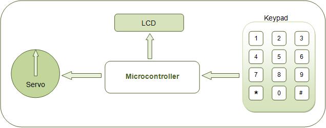
The basic operations of servo motor control have been discussed in interfacing servo with 8051. This project allows the servo motor to move to an angle specified by the user. The pulse train required to rotate the servo is produced by AT89C51 microcontroller. The desired angle of rotation is provided through a 4x3 keypad interfaced to the microcontroller. A 16x2 LCD is also connected with the microcontroller to display the angle of rotation entered by the user.
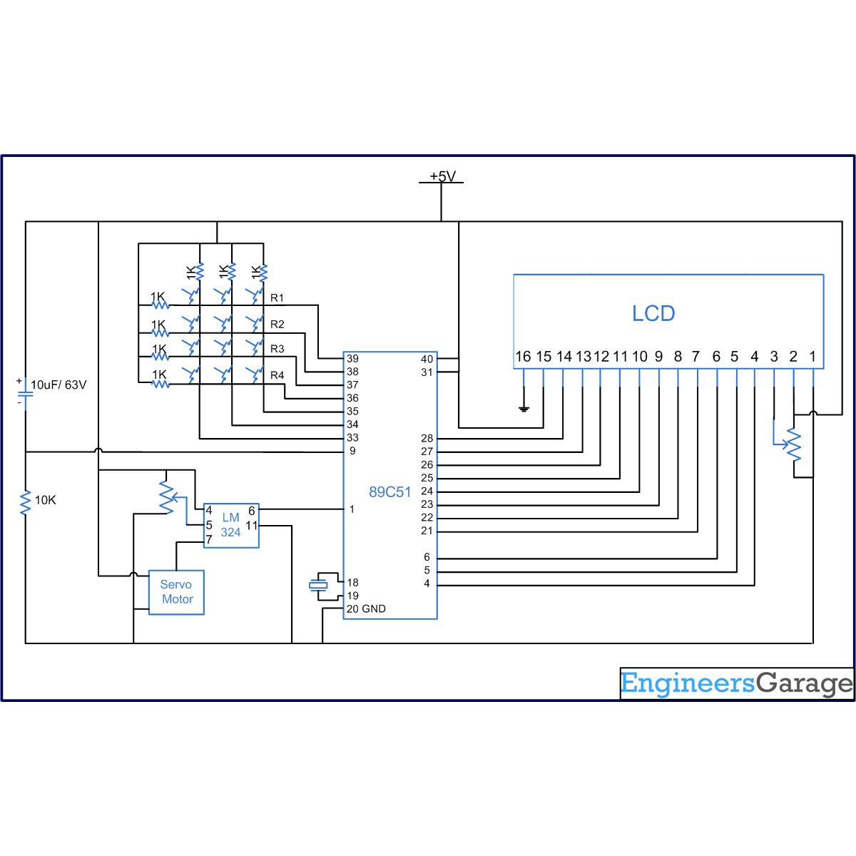
For basic operations and control of servo motor, refer interfacing servo with 8051. The first pin of port P1 (P1^0) of AT89C51 microcontroller is set as the output pin to provide control signal to the servo motor. Ports P0 and P2 are used to interface keypad and data pins of LCD, respectively. Ports P1^3, P1^4 and P1^5 are connected to RS, RW and EN pins of LCD, respectively. (For more details, refer LCD interfacing with 8051)

Fig. 2: Block Diagram of Servo Output Of Microcontroller
Before connecting to the control wire of servo, the output from the microcontroller (P1^0) is fed through a comparator IC (LM324) so that the signal is protected from any loss due to overloading.
When the circuit is powered, the LCD prompts the user to enter the angle of rotation. The user can enter the angle in degrees through keypad. The angle entered by the user is also displayed on the LCD screen. As the user presses ‘*’ button of keypad, the angle of rotation is accepted by the microcontroller and the servo moves to the user defined angular position. If an angle greater than 180° is entered, the difference of the input with 180° is considered as the angle of rotation.
The program uses one of the 8051 timers to generate a 50 µs delay. A timer function is written which produces delay in multiples of 50 µs. A variable is taken as the argument to this function that determines the multiples. Initially when the microcontroller executes program, a pulse with ON time of 700 µs (14 x 50 µs) followed by OFF time of 18 ms is generated. This shifts the servo horn to 0° angle.
The angle entered by the user is stored in a variable whose value is added to the argument of the timer function. For example, if the user enters 90, the argument of the timer function is increased by 90 and becomes 104 (90 + 14). The ON time for the next train of pulses then corresponds to multiple of 50 µs. In this case the ON time of the next train of pulses will be 5200 µs (104 x 50 usec) followed by OFF time of 18 ms. This maintains the servo at 90° angle until the user enters the next angle.
Project Source Code
###
// Program to rotate servo to user defined angular position // 0 degree = 700us // 180 degree = 5500us // Timer1 pulse after 50us -23 #include<reg51.h> #define dataport P2 // Data port for LCD #define key P0 // Port for Keypad #define port P1 sbit output = port^0; sbit rs = port^3; sbit rw = port^4; sbit en = port^5; sbit col1 = key^4; sbit col2 = key^5; sbit col3 = key^6; sbit row1 = key^0; sbit row2 = key^1; sbit row3 = key^2; sbit row4 = key^3; int count=0,time=0,check, digit[3]; void delay(unsigned int msec) // Function for delay { int i,j; for(i=0;i<msec;i++) for(j=0;j<1275;j++); } void lcd_cmd(unsigned char item) // Function to send command to LCD { dataport = item; rs= 0; rw=0; en=1; delay(1); en=0; return; } void lcd_data(unsigned char item) // Function to send one byte data to LCD { dataport = item; rs= 1; rw=0; en=1; delay(1); en=0; return; } void lcd_data_string(unsigned char *str) // Function to send string to LCD { int i=0; while(str[i]!='�') { lcd_data(str[i]); i++; delay(10); } return; } lcd_data_int(int time_val) // Function to send three digit number { int int_amt; int_amt = time_val/100; lcd_data(int_amt+48); time_val = time_val%100; int_amt = time_val/10; lcd_data(int_amt+48); int_amt = time_val%10; lcd_data(int_amt+48); } void shape() // Function to make degree sign { lcd_cmd(64); lcd_data(2); lcd_data(5); lcd_data(2); lcd_data(0); lcd_data(0); lcd_data(0); lcd_data(0); lcd_data(0); } void timer(int msec) // Function to produce pulse as defined by user { int i; TR1=1; for(i=0;i<msec;i++) { while(TF1==0); TF1=0; } TR1=0; } void digit_set(int num) { if(count==4) { lcd_cmd(0x01); lcd_data_string("done"); check=num; } else { check=0; if(count==1) digit[0]=num; else { if(count==2) { digit[1]=digit[0]; digit[0]=num; } else if(count==3) { digit[2]=digit[1]; digit[1]=digit[0]; digit[0]=num; } } lcd_data((num+48)); } } void check_col1() // Col1 check { row1=row2=row3=row4=1; row1=0; if(col1==0) // Key 1 { delay(10); count=count+1; digit_set(1); } row1=1; row2=0; if(col1==0) // Key 4 { delay(10); count=count+1; digit_set(4); } row2=1; row3=0; if(col1==0) // Key 7 { delay(10); count=count+1; digit_set(7); } row3=1; row4=0; if(col1==0) // Key * { delay(10); count=count+1; if(count==4) { digit_set(10); } else { count=4; digit_set(10); } } row4=1; } void check_col2() //Col2 check { row1=row2=row3=row4=1; row1=0; if(col2==0) // Key 2 { delay(10); count=count+1; digit_set(2); } row1=1; row2=0; if(col2==0) // Key 5 { delay(10); count=count+1; digit_set(5); } row2=1; row3=0; if(col2==0) // Key 8 { delay(10); count=count+1; digit_set(8); } row3=1; row4=0; if(col2==0) // Key 0 { delay(10); count=count+1; digit_set(0); } row4=1; } void check_col3() // Col3 check { row1=row2=row3=row4=1; row1=0; if(col3==0) // Key 3 { delay(10); count=count+1; digit_set(3); } row1=1; row2=0; if(col3==0) // Key 6 { delay(10); count=count+1; digit_set(6); } row2=1; row3=0; if(col3==0) // Key 9 { delay(10); count=count+1; digit_set(9); } row3=1; row4=0; if(col3==0) // Key # { delay(10); count=count+1; lcd_data_string("wrong data"); lcd_cmd(0x01); lcd_data_string("enter degree:"); lcd_cmd(0xc5); count=0; } row4=1; } void keypad() { if(col1==0) check_col1(); else if(col2==0) check_col2(); else if(col3==0) check_col3(); delay(10); } void main() { int i; col1=col2=col3=1; TMOD=0x20; // MODE2 TH1= -23; // 50 usec timer shape(); output=0; lcd_cmd(0x38); lcd_cmd(0x0e); lcd_cmd(0x01); delay(100); while(1) { count=0; lcd_cmd(0x01); lcd_data_string("enter degree:"); lcd_cmd(0xc5); check=0; digit[0]=0; digit[1]=0; digit[2]=0; while(check!=10) { row1=row2=row3=row4=0; while(col1==1 && col2==1 && col3==1); keypad(); } time=(digit[0]+(digit[1]*10)+(digit[2]*100)); lcd_cmd(0xc4); time=time%180; lcd_data_int(time); lcd_data(0); time= time*0.5; // (110-14)/180=0.53 for(i=0;i<200;i++) { output=1; timer(14); output=0; timer(360); } delay(100); for(i=0;i<200;i++) { output=1; timer(time+14); output=0; timer(360); } timer(3000000); } }###
Circuit Diagrams
Project Components
Project Video
Filed Under: 8051 Microcontroller.
Filed Under: 8051 Microcontroller.


Questions related to this article?
👉Ask and discuss on Electro-Tech-Online.com and EDAboard.com forums.
Tell Us What You Think!!
You must be logged in to post a comment.