The LED starts glowing as intensity of sound varies. This project can be used to measure the intensity of sound present in the room as sound intensity increase [[wysiwyg_imageupload::]]number of LED glows also increases. Circuit is based on LM324 which is 14 pin IC consisting of 4 independent operational amplifiers. The output voltage of LM324 is many times higher than the voltage difference between the input terminals of an op amp.LM324 IC is used as a comparator and when input voltage rises above the reference voltage, output is attained. When no noise or audio signals are present in the room, output voltage on pin 1 is zero as voltage on pin 2 is lower than that at pin 3. Since, the IC works as comparator, less voltage on pin 2 in comparison to pin 3 will not make the LED glow. Let’s find out the working of this interesting project.
Led Lighting

The dazzling Water Cube swimming arena at last summer’s Beijing Olympics was lit up by around half a million LEDs. Famous Bridges, buildings and hotels are opting LEDs for their exquisite night lighting and general illumination too. Why there is this sudden rage for the tiny LED? A little light emitter, a well renowned indicator that faithfully served in the display units of calculators, digital watches, and mobile phones for years is now geared up to take away the headache of efficient as well as Eco-friendly lighting.Yes, the tiny LED is all set to light our lives. It has taken a giant leap, from being a humble indicator to on the way to monopolize the lighting market. Years of research has brought LEDs to this advanced stage.
Insight – How LED Light Bulb works
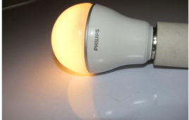
LED bulbs are the future of lighting. Be it automobiles, industries, household or any hobbyist requirement, LEDs form the best solutions in terms of long-term cost savings and power efficiency. Not only are these devices more efficient than traditional lighting devices, they are built to outlast any of their lighting predecessor. The internals of a typical LED bulb will be explored here.Externally, a LED bulb might look similar to a conventional incandescent lamp, but the two are quite different. The chassis of the bulb is made of ceramic and houses the electronic ballast. Ceramic is used for its insulating and heat dissipative properties.
Led Flasher Circuit
The operation of the LED flasher circuit project is based on 555 timers with few other components. It flashes the LED ON and OFF after regular intervals of [[wysiwyg_imageupload::]]time. It can be used as eye of a toy to find the toys in the dark, in events like wedding ceremonies, birthday parties or any other events to grab the attention. The LED Flasher circuit project here is based on 555 timers. The timer is wired in astable mode which means that its output is a square wave oscillator. The two LEDS are connected in such a way that when one is ON other is OFF and vice versa. Keep on reading to find out how the circuit is constructed and how it works.
Bi Color LED
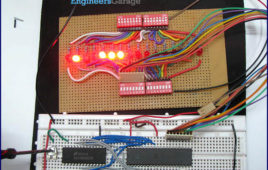
This circuit uses Bi-color LED which creates an eye-catching running display effect. This project can be used in the places like borders of animation, pictures, [[wysiwyg_imageupload::]]short word display etc. The bi-color LEDs are similar to uni-color with the difference that there are two LEDs housed in a package. Bi-colour LEDs may have two or three leads depending upon the internal connections. In this circuit five Bi-color LEDs are used. The LEDs first light in green color, from top to bottom and then in red color, from bottom to top. The IC1 provide clock pulses to the input of decade counter IC2. At each clock pulse, IC2 counts from 0 to 9. The first five pulses lights up in green color when they reach the green anodes of the bi-color LED. Similarly, next five pulses lights up in red color when they reach the red color anodes.
Computer Monitors – CRT, LCD, LED, Plasma & OLED Display Monitors
A computer monitor, technically termed as visual display unit is an output device that presents the information from the CPU on the screen working as an interface between CPU and the user. A cable connects the monitor to a video adaptor or video card which is set up on the motherboard of the computer. The CPU (Central Processing Unit) sends instruction to the video adaptor telling what needs to be displayed on the screen. The video adaptor converts the instructions into a set of corresponding signals and sends to the monitor. Monitor contains a circuitry that generates the picture on the screen from the set of signals. The major parameters that measure the performance of a monitor are luminance, contrast ratio, resolution, dot pitch, response time, refresh rate and power consumption. The common problem that arises in monitors is dead pixels, blurred screen, phosphor-burn, etc.
Difference Between LCD and LED Display
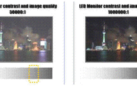
LCD (Liquid Crystal Display) and LED (Light Emitting Diode) Displays are two major display technologies being widely used today. LED Displays are technological advancement of LCD displays. LED displays are the LCD displays with an LED backlight to power up the LCD panel. It means that LEDs are placed behind or around the LCD panel…
Insight – How LED works
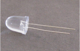
LED (Light Emitting Diode) is a special diode that emits light when an electric voltage is applied to it. It is common electronic component that is being used in devices like TV, computer, etc. generally for indicating purpose. They are available in various colors like red, yellow, green etc. There are two leads of an LED that are used to supply input voltage. The longer lead is positive and known as ‘Post’, and the smaller is negative known as ‘Anvil’ as shown in the image above. A metal cup is placed on the negative lead (Anvil) which holds a semiconductor die. The semiconductor die is a combination of two semiconductor materials – N type and P type and an active region (known as P-N junction) between them.
Insight – How Soldering Iron Works
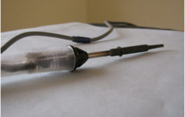
Soldering iron is quite popular hand tool commonly used to solder components with each other. It works on a very basic principle. When we pass current through a high resistant material, heat is generated. We use this heat to melt down a conductor metal also called soldering wire and putting it between two components in order to connect them electrically.A general soldering iron consists of a heating region and an insulated handle. On supplying electrical current to the soldering iron, the heating tip gets heated and with the help of a soldering wire it joins two components.
Insight – How Seven Segment Display works
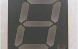
In 1910 Frank W. Wood made a board which can display number and after several modifications today it’s called7-segment display. 7 segment display is a 10 [[wysiwyg_imageupload::]]pin electronic component with eight led’s embedded inside it to displays number from 0 to 9.It is available in two configurations: common cathode and common anode. All the 8 LED terminals have their one end internally shorted and linked with the middle pins such that it serves as a common terminal (cathode or anode). Middle pin of both sides are shorted with each other which serves as a common terminal. 7 led are used to form the digits while the 8thone is for the dot which helps in identifying the correct orientation. Read more to find out how internal features of 7-segment display and know how it works.
Moving LED Display
Moving LED Display is very active application of digital electronics. The application of this device can be found everywhere. From name plate display to train number display this display is used. The power consumption is 70% less than primitive display. The main advantage of using this display is the information displaying on the display can easily be change by changing the program in microcontroller. And also animation is possible during displaying the massage. This is undoubtedly acceptable in the high society. There is another advantage of this device i.e. less cost-effective. The LED used in this device is RED LED having wavelength 660nm. Hence the displaying massage can be seen from very high distance.
How to take input from a particular pin of ATmega16- (Part 5/46)
For understanding the human needs a system must be able to take input from user. The devices which can be used to take input for a system are keypad, touch [[wysiwyg_imageupload::]]screen, etc. In the article LED blinking, the microcontroller drives the LED or in embedded language the microcontroller was set to give o/p, this article gives brief information of getting an input from user at a particular pin of microcontroller. In order to take input from an external source on any of the pins of the AVR microcontroller, the pins need to be configured as input pin. This configuration informs the controller that the corresponding pins are used to take input. Read more to find out how the circuit is constructed and how the IC can be programmed to work in the desired manner.
How to interface LED with AVR Microcontroller (ATmega16)- (Part 4/46)
ATmega16 has 32 I/O pins to communicate with external devices. Before interfacing with external devices, these pins must be cofigured as input or output pin. [[wysiwyg_imageupload::]]This article demonstrates the basic I/O operation of ATmega 16 using LEDs. All the four ports can be configured to read an input from some external device or to give output to any external device as per the application. For e.g., a switch is connected to a particular pin, that pin should be configured as input to read the values from the switch (external Device in this case) and if you are connecting a LED to any pin of the port then that particular pin should be configured as output to transmit the signal to the LED (external device in this case). A single port can be configured such that some of the pins of the same port are input and some are output. Read on more to understand how LED interfacing is done with the help of an AVR.
How to interface ADC0808 using clock from 8051 microcontroller (AT89C51)- (Part 25/45)
An analog-to-digital converter is a device which converts continuous signals to discrete digital numbers. Typically, an ADC is an electronic device that converts [[wysiwyg_imageupload::]]an input analog voltage (or current) to a digital number proportional to the magnitude of the voltage or current. This circuit demonstrates the interfacing ofADC0808 using 8051 microcontroller (AT89C51). The digital output is taken on a set of LEDs. This is an intermediate circuit which finds several applications. This circuit depicts a way to provide the external clock, required for ADC, from the microcontroller.Analog-to-digital converters are among the most widely used devices for data acquisition. Digital computers use binary values, but in physical world everything is analog. Therefore, we need an analog-to-digital converter to translate these analog signals to digital signals.An ADC has n-bit resolution where n can be 8,10,12,16 etc. The ADC chips are either parallel or serial. Parallel ADC has 8 or more pins dedicated to bring out the binary data. ADC0808 is such a parallel ADC with 8-bit resolution.
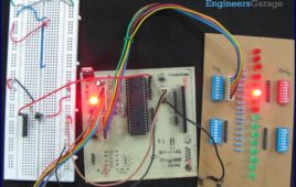
Automatic bidirectional visitor counter using 8051 microcontroller (AT89C51)

A counter that can change its state in either direction, under control of an up–down selector input, is known as an up–down counter. The circuit given here can [[wysiwyg_imageupload::]]count numbers from 0 to 9999 in up and down modes depending upon the state of the selector. It can be used to count the number of persons entering a hall in the up mode at entrance gate. In the down mode, it can count the number of persons leaving the hall by decrementing the count at exit gate. It can also be used at gates of parking areas and other public places.This circuit divided in three parts: sensor, controller and counter display. The sensor would observe an interruption and provide an input to the controller which would run the counter in up/down mode depending upon the selector setting. The same count is displayed on a set of 7-segment displays through the controller. Read more to find out about working of the circuit and how microcontroller is coded.
How to interface LEDs with 8051 microcontroller (AT89C51)- (Part 1/45)

This article introduces you to the very basic operation of taking an output from the microcontroller AT89C51. It demonstrates the principle behind interfacing LEDs [[wysiwyg_imageupload::]]with 8051 microcontroller. Here we have demonstrated the aforesaid principles by blinking LEDs continuously i.e., switching them on and off.AT89C51, which belongs to the family of 8051 series of microcontrollers, is very commonly used by a large community of hobbyist and engineers. Its simplicity and ease of programming with inbuilt features easily makes its position in the top preferred list of microcontroller for both beginners and advanced user. LEDs need approximately 10mA current to flow through them in order to glow at maximum intensity. However the output of the controller is not sufficient enough to drive the LEDs, so if the positive leg of the LED is connected to the pin and the negative to ground as shown in the figure, the LED will not glow at full illumination.
Display custom characters on LCD using AVR Microcontroller (ATmega16)- (Part 9/46)

This is the most interesting article to play with LCD. After going through the article, you can create any character/symbol which cannot be created using the [[wysiwyg_imageupload::]]ASCII values for example smiley. You can even create small games. Conventionally 16X2 LCD is use to display text or numerical values. It is possible to display special characters, your own designed characters too on LCD by using its 5 x 8 matrix block. These special characters are stored in the CGRAM of LCD. This article shows how to create and display special character on LCD using ATmega16. For more details refer to the article how to create custom characters. This article assumes that the readers are aware of the concepts of interfacing LCD with AVR microcontroller (ATMEGA 16). For more information about interfacing LCD with AVR, refer How to display string on LCD using AVR. In order to create a custom character its configuration is first defined in the CGRAM of the LCD. A maximum of eight characters can be stored at a time in the 16 x 2 LCD.
Seven Segment Multiplexing using PIC18F4550 Microcontroller- (Part 4/25)

As explained earlier, a seven segment interfaced with PIC uses almost an entire port (minimum 7 pins) to display a value. But a real time application, like watch, [[wysiwyg_imageupload::]]calculator etc., usually requires at least 3-4 seven segments. In such a case it is not advisable to use a port of the controller for each seven segment. In these cases, multiplexing technique is used to work with more than one seven segment. Here multiplexing of four seven-segments has been explained withPIC18F4550 to display four-digit count from 0000 to 9999. The multiplexing concept is based on the principle of persistence of human vision. A human eye cannot detect a visual change if the frames change at a rate of 25 (or more) frames per sec. This means that if events occur continuously with a time difference of less than or equal to 0.04 sec (1/25 sec), then we cannot notice the transition between those events.
How to take input with PIC18F4550 Microcontroller- (Part 2/25)

Any microcontroller based system typically has an input and a corresponding output. Taking simple output with a PIC microcontroller has been explained inLED [[wysiwyg_imageupload::]]blinking with PIC18F4550. This article explains how to provide an input to the controller and get a corresponding output using PIC18F4550. PIC18F4550 has a total of 35 I/O (input-output) pins which are distributed among 5 Ports. Each Port of a PIC microcontroller corresponds to three 8-bit registers (TRIS, PORT & LAT) which should be configured to use the Port for general I/O purpose. For more details, refer LED blinking using PIC.To configure a particular port/pin as input, the corresponding TRIS register/TRIS bit should be set to high (1). For output, the relevant TRIS register/bit should be set to low (0). Read on to know more about PIC micro controller and get a step by step approach to take input with PIC. A must learn for every budding PIC enthusiast.
How to interface Seven Segment Display with PIC18F4550 Microcontroller- (Part 3/25)

A typical seven-segment consists of 8 LEDs arranged in a pattern to display values. A seven-segment can be either of the two types, namely, Common Anode (CA) and Common Cathode (CC). For more details, refer Seven segments. A single seven-segment requires a minimum of 7 data pins of controller to display different values. The connections…