
Maxim Integrated Products, Inc. has introduced the four-channel, low-voltage MAX25512, automotive LED backlight driver with integrated boost converter. It’s the only integrated solution that retains full, constant brightness of in-car displays even during extreme cold crank conditions down to 3V input voltage. The single-chip LED driver eliminates an external MOSFET and current-sense resistor, integrating I2C…
STMicroelectronics launches flexible automotive LED driver

STMicroelectronics’ ALED6000 single-chip automotive LED driver with integrated DC/DC converter is a low-BoM (Bill of Materials) solution that allows design flexibility and keeps the lighting intensity consistent as electrical conditions within the vehicle fluctuate. Suitable for exterior lighting such as daytime running lights, headlights, rear lights, stop lights, and turn signals, as well as interior lighting, the…
Diodes launches new automotive-compliant LED driver

Diodes Incorporated has expanded its portfolio of devices supporting automotive exterior illumination with the introduction of the AL5873Q three-channel linear LED driver, targeted at simplifying rear lamp cluster designs. Rated for 125° C ambient-temperature operation, this automotive-compliant, AEC-Q100 Grade 1 qualified device meets the demands of next generation vehicle design. It also providing energy and…
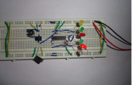
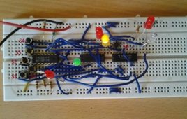
Operating Daily Life Gadgets using Voice Recognition System and Embedded Controllers

Introduction 1.1 GENERAL This chapter deals with the objective and unique features of the project and the organisation of the report. 1.2 OBJECTIVE The objective of the project work is to build an aid for physically challenged people to enable them operate normal daily life gadgets easily and conveniently using a voice recognition…
Insight – How an LED dot matrix display works
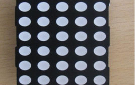
Light emitting diodes aligned in a form of matrix constitute a dot matrix display. It is commonly used to display time, temperature, news updates and many more on digital billboards. Dot Matrix Display is manufactured in various dimensions like 5×7, 8×9, 128×16, 128×32 and 128×64 where the numbers represent LEDs in rows and columns, respectively.Arrangement of the LEDs in the matrix pattern is made in either of the two ways: row anode-column cathode or row cathode-column anode. In row anode-column cathode pattern, the entire row is anode while all columns serve as cathode and vice-versa pattern is there in row cathode-column anode. LED wafers are glued to the bottom of the segments and glow when powered ON. The interesting part is that 35 LEDs are controlled by using a combination of 14 pins. Conductor tracks are laid all over the board to power each LED. Let’s proceed to know in depth about how a dot matrix display works.
Music Operated LED
This circuit will light up different LED’s according to the audio signals which are feed through condenser microphone. When sound intensity is low few LED’s will glow as intensity of sound increases number of LED’s which glow also increases. Important feature of this circuit is we have not use any special running light IC like LB1405. We have made this circuit with the help of seven channel Darlington array IC ULN2003. ULN2003 is a monolithic high voltage and current Darlington transistor array. It contains seven NPN Darlington pair on a single IC. It also have high output voltage with common cathode clamp diode for switching inductive load. And collector current rating of each Darlington pair is 500mA. Another feature of ULN2003 IC it has 2.7kW series base resistor for each Darlington pair so that it can directly connected to TTL or 5V CMOS device. Read more to find out how this circuit is assembled and how it is made to work.
DIY – Table Lamp
Ever wanted to make your own table lamp? If yes then you have come to the right tutorial! This project shows you how to make table lamp using a bunch of LEDs and 555 Timer circuit. Our first problem is that we can’t give 12V directly to an LED which would simply burn it. Well you may say that adding a series resistor would solve that problem but let’s see what happens when we do that.
Dot Matrix Display using Arduino

This project is based on Arduino Platform. In Electronics, there are many display devices available in or market like Liquid Crystal Display, Seven Segment Display, Dot Matrix LED display, Graphic Display etc. and they are used to display some information in many places like railway station, bus stand, mall, multiplex, hospital, school, colleges and many other places.Here, In this circuit Dot Matrix LED display is used for displaying information. The method of displaying message on dot matrix displays is same as seven segment multiplexing. Column of dot matrix is rotating very fast means greater then seventeen times in a second and same time changing in row data causes display some information on it. Due to the vision of our eye it looks like stable.
Controlling RGB LED colour using Atmega16- (Part 19/46)
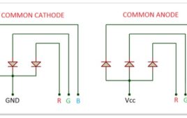
This tutorial will give you a brief introduction to the concept of colors and how different colors can be produced using RGB LED. The color would be controlled using an ATMega16 microcontroller.RGB LEDs are basically the combination of the 3 LEDs (Red, Green and Blue) fused into a single package. It consists of four pins totally out of which three of them for the three different colors. The 4th pin is common for all three colors and it’s either Cathode or Anode.
LED Based Stop Watch
This LED based stop watches circuit can be worked as a clock in this counter will advance after every one second. When you provide power supply it start it’s counting from zero and you can stop the timer any time with the help of switch.In this circuit you can monitor the time from 1 second to 60 minutes. It can be used while cooking or while doing exercise or in laboratories. It can be used by students preparing for competitive exams. Important feature of this circuit is you can switch off the stop watch any time with the help of switch S1 and it will hold that value. Keep on reading to find out how the circuit is assembled and how it is put to use.
How to Blink LED using Raspberry Pi -(Part 07/38)

The Intel and ARM are the two popular processor families widely used in computational device. The Intel processors are mostly used in the Personal Computers whereas the ARM processors are optimized for the embedded system applications. The high end ARM processors can provide embedded system devices with that much computational power as most of the PCs have. The Raspberrypi is a low cost minicomputer board designed to be used as a PC for providing computer education for remote schools, where costly desktops are not available. The embedded system people are interested in it since it is using ARM11 processor based microcontroller and unlike the motherboard of the PC, the Raspberry pi board provides lot of pin outs like GPIO pins, serial communication pins etc. which enable them to be used in embedded system applications.
Clock with LED pendulum with tick tock sound

Many of us see different kinds of wall clock available in market which produces sound but they are very expensive. The circuit described here produces a tick tock sound and also indicate the time with the help of LED. In this circuit, LED’s are arranged such that you will get time in the form of a pendulum first in one direction than in opposite direction. So you can make your own watch in much less price as compared to market.This simple circuit is based on two IC’s namely NE555 timer and CD4017 with few more discrete components. 555 timer IC wired as an a-stable oscillator. In this circuit NE555 a-stable generates a clock for the Circuit, which provide a oscillating wave to the output pin 3 of IC1. You can vary the speed of oscillation with the help of R2.
Switch Status & LED with AVR microcontroller- (Part 6/46)
Generally we know about interfacing button switches, LED with Atmega32 microcontroller. We know that interface switch’s to one port, LED’s to another port and if we press any switch the corresponding LED will glow. But all the LED’s operate with single switch we don’t know. Here we are developing the program for operating 7 LED’s with one switch. The circuit connections and programming is so simple. We will discuss here about that. First we see the circuit connections. Let us take any one port of Atemga32 controller is PortD. Connect 7 LED’s to PortD and connect on switch to remaining pin of the PortD. Now let us start the coding for microcontroller. First open the Atmel Studio software of any version. Create a new project with your desired file name. Here I am taking the project name as “button switch”.
Dancing LED’s
The circuit is used for decoration purpose or as an indicator. Flashing or dancing speed of LED’s can be varied with the help of variable resistor and various dancing pattern of light can be formed by slight change in the circuit. In this circuit 6 LED’s moves in one direction then again flow the opposite direction than previous. The circuit is based on two IC’s namely NE555 and CD4017 with few more components. 555 timer IC wired as an astable oscillator. In this circuit NE555 astable generates a clock for the circuit which provide a oscillating wave to the output pin 3 of IC1. You can vary the speed of oscillation with the help of VR1. The frequency of oscillation of 555 timer can be calculated by f=1.44/(R1+2*(VR1)*C1) and CD4017 is a CMOS counter/ divider IC. It take clock signal from the clock input and turn on the 10 output in sequence, each time when it receives clock input pulses. It is the most popular IC and extremely useful in various project like Light Chaser, Matrix Die. In order to understand the working of IC one must know about its individual pin.
Implemetation of BODMAS Rule using IC’s
Everyone has studied this rule in their childhood. It stands for “bracket, “off”, “division”, “multiplication”, “addition”, “subtraction”. A mathematical operation involve a number of operators but they must carry out in a particular order. The circuit described here will help you to practically implement the BODMAS rule which we have studied.The circuit is made with the help of three IC’s namely 7404, 7408 and 4073. 7404 is a hex inverter or NOT gate IC. It is a 14 pin IC and contain 6 individual NOT gate on a single IC. 7408 is a quad 2 input AND gate IC. It contains 4 individual AND gate on a single IC. 4073 is a triple 3 input AND gate. It contains 3 individual AND gate on a single IC. LED, switches and resistors are also used in this circuit.
LED Based Pendulum Circuit
The circuit is based on two IC’s namely NE555 and CD4017 with few more components. where 555 timer IC is wired as an astable oscillator. CD4017 is a CMOScounter/ divider IC which takes clock signal from the clock input and turns on the10 output in sequence, each time when it receives clock input pulses. It is the most popular IC and is extremely useful in various project like Light Chaser, Matrix Die.The circuit is based on two IC’s namely NE555 and CD4017 with few more components. where 555 timer IC is wired as an astable oscillator. CD4017 is a CMOS counter/ divider IC which takes clock signal from the clock input and turns on the10 output in sequence, each time when it receives clock input pulses. It is the most popular IC and is extremely useful in various project like Light Chaser, Matrix Die.
IC555 based Multicolor LED Lamp Circuit Diagram
NE555 astable generates a clock for the circuit, which provides an oscillating wave to the output pin 3 of IC1. You can vary the speed of oscillation with the help of VR1. The frequency of oscillation of 555 timer can be calculated by: f=1.44/(R1+2*(VR1)*C1) Now this wave is supplied to CD4017 decade counter pin 14…
Multimeter Tutorial: How to Test LED

Step 1: Understanding the component Fig. 1: Image of an LED Light emitting diode (LED)is a small component used in almost every electronic device. Led has 2 terminals or legs. The bigger leg is the anode or positive terminal and shorter leg is cathode or negative terminal. But this method of identifying the leads will not…
CD 4027 Based Emergency Lighting System
Described here is a CD 4027 hearted, battery employed circuit that serves as a solution for light and fan during the times of extreme humidity or power cuts. The circuit consists of a LED light and small DC fan which can sufficiently work for one person. The main advantage of this circuit is one can use any one or both devices at a particular time. The circuit does not consume much power so one can expect it work for a good amount of time. This circuit is based on CD4027 IC which is the most commonly used JK flip flop IC. CD4027 is the master slave JK flip flop IC which works in toggle mode. Here, this IC can be used to change the state by signal applied to one or more control inputs and will have one or two outputs. In this circuit, output is only depended upon the current input.
CD4049 Based LED torch
A simple LED torch would light up 3 white LED from 6 volts supply in case of emergency or in darkness. It is quite light-weight and handy, thus, can be used [[wysiwyg_imageupload::]]while traveling in train or in bus. Here we have used CD4049 IC which is a hex inverting buffer CMOS chipCD4049 contains six inverter gates in one package as shown in diagram. In this, pin 3 is input and 2 is for output. For first gate similarly pin 5 is input and pin 4 is output for second gate similarly we have four more gates. Pin1 1 is for supply voltage and pin 8 is connected to ground. Pin 13 and 16 are unused. The circuit is based on NOT gate CD4049 IC and utilizing 3 gates of NOT gate IC.