I2C and SPI are two of the most widely used serial communication buses for embedded systems — and each comes with its own set of advantages and disadvantages. SPI is the faster protocol, but it’s more costly and offers limited scalability. To close this trade-off gap between I2C and SPI in Serial EEPROMs, Microchip Technology has…
SPI: What is the Serial Peripheral Interface Protocol?
SPI protocol has earned a solid role in embedded systems whether it is system on chip processors, both with higher end 32-bit processors such as those using ARM, MIC or Power PC and with other microcontrollers such as the AVR, PIC etc. These chips usually include SPI controllers capable of running in either master or slave mode. In-system programmable AVR controllers can be programmed using an SPI interface.Chip or FPGA based designs sometimes use SPI to communicate.
GETTING STARTED WITH CAN INTERFACE WITH ARDUINO
This Article is to make readers to explore about how to interface CAN Bus with Arduino which is used in the Communication of Sensors, Actuators and controllers in a car.This project helps in understanding the insights of CAN protocol interfacing with Arduino. Controller Area Network or CAN protocol is a methodology of communication between various electronic devices like engine management systems, gear control, active suspension, ABS, lighting control, air conditioning, airbags, central locking etc. embedded in an automobile. For further learnings refer this article.
How To Test The SPI Module Of Arduino- (Part 32/49)
Any AVR microcontroller based board which follows the standard arduino schematic and is flashed with the arduino boot-loader can be called an arduino board. All arduino boards should be compatible with the arduino IDE which can be used to program the arduino boards. The arduino IDE is also open source and anybody can contribute their libraries to the arduino. The arduino is refered to as open source hardware, since the standard schematic is open to everyone and anybody can make their own version of arduino board following the standard schematic.Since the Arduino board can act as a stand-alone system it should have capabilities to take inputs process the input and then generate a corresponding output. It is through these inputs and outputs that the Arduino as a system can communicate with the environment.
How to Implement SPI Using PIC18F4550- (Part 24/25)
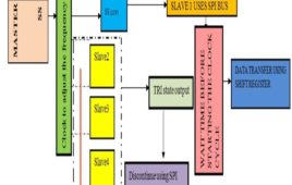
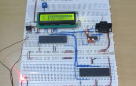
The Serial Peripheral Interface (SPI) is a high speed, synchronous, serial communication standard. This communication protocol is basically a Master – Slave implementation where the master device controls the clock based on which the slave devices operate. The master communicates with a slave or a number of slaves in a system through the SPI bus. The SPI bus requires a minimum of three wires including SDO (Serial Data Out), SDI (Serial Data Input) and SCK (Serial Clock). Since it is a master controller system the SDO is also called MOSI (Master Output Slave Input) and the SDI is also called MISO (Master Input Slave Output). The SPI is a full-duplex high speed communication protocol. The master and slave can transmit and receive data at the same time. The master is the device which generates clock for all these data transmissions. Read PIC microcontroller tutorial based on PIC18F4550 microcontrollers in which one of the microcontroller acts as a slave transmitter and the other acts as master receiver. With the help of an LCD, this particular project demonstrates the complete data transfer between a master and slave when both the master and slave are transmitting and receiving the data at the same time.
How to use PIC18F4550 as a SPI Slave Transmitter- (Part 25/25)
The Serial Peripheral Interface (SPI) is a high speed, synchronous, serial communication standard. This communication protocol is basically a Master Slaveimplementation where the master device controls the clock based on which the slave devices operates. The master can communicates with one or more slave in the system through SPI bus. The SPI bus requires a minimum of three wires i.e. a SDO (Serial Data Out), SDI (Serial Data Input) and SCK (Serial Clock). Since it is a master controller system the SDO is also called MOSI (Master Output Slave Input) and the SDI is also called MISO (Master Input Slave Output).The SPI is a full-duplex high speed communication protocol. The master and slave can transmit and receive data at the same time. The master generates clock for all these data transmissions.The SPI is special because it is simple and easy to implement in the hardware. The article explores the SPI hardware module of the PIC18F4550 microcontroller. This project will help in better understanding of the SPI protocol in detail.
SPI (serial peripheral interface) using AVR microcontroller (ATmega16)- (Part 37/46)
There are different protocols for serial communication between two deceives like, USART, SPI, I2C etc. Before selecting any communication protocol, data transfer [[wysiwyg_imageupload::]]rate is an important parameter. SPI transfers data at high speed data. AVR microcontroller contains on chip SPI interface. This article will explore the hardware configuration and programming of SPI. Serial Peripheral Interface is a synchronous, full-duplex protocol. SPI is also known as “3-wire interface” protocol because it needs 3 communication lines named MISO, MOSI and SCK. SPI protocol needs two devices for communication. One of them is considered as a MASTER and another one as a SLAVE.AVR microcontrollers contain both MASTER and SLAVE interface on single chip. Thus, a microcontroller can work as both master and slave device. The SPI is synchronous data transfer protocol, so clock pulse is needed to synchronize both master and slave device. The clock pulse is generated from master side. The SCK pin of master provides clock pulse to slave device.


