Engineers Garage

  • Electronics Projects and Tutorials
    • Electronic Projects
      • Arduino Projects
      • AVR
      • Raspberry pi
      • ESP8266
      • BeagleBone
      • 8051 Microcontroller
      • ARM
      • PIC Microcontroller
      • STM32
    • Tutorials
      • Audio Electronics
      • Battery Management
      • Brainwave
      • Electric Vehicles
      • EMI/EMC/RFI
      • Hardware Filters
      • IoT tutorials
      • Power Tutorials
      • Python
      • Sensors
      • USB
      • VHDL
    • Circuit Design
    • Project Videos
    • Components
  • Articles
    • Tech Articles
    • Insight
    • Invention Stories
    • How to
    • What Is
  • News
    • Electronic Product News
    • Business News
    • Company/Start-up News
    • DIY Reviews
    • Guest Post
  • Forums
    • EDABoard.com
    • Electro-Tech-Online
    • EG Forum Archive
  • DigiKey Store
    • Cables, Wires
    • Connectors, Interconnect
    • Discrete
    • Electromechanical
    • Embedded Computers
    • Enclosures, Hardware, Office
    • Integrated Circuits (ICs)
    • Isolators
    • LED/Optoelectronics
    • Passive
    • Power, Circuit Protection
    • Programmers
    • RF, Wireless
    • Semiconductors
    • Sensors, Transducers
    • Test Products
    • Tools
  • Learn
    • eBooks/Tech Tips
    • Design Guides
    • Learning Center
    • Tech Toolboxes
    • Webinars & Digital Events
  • Resources
    • Digital Issues
    • EE Training Days
    • LEAP Awards
    • Podcasts
    • Webinars / Digital Events
    • White Papers
    • Engineering Diversity & Inclusion
    • DesignFast
  • Guest Post Guidelines
  • Advertise
  • Subscribe

A filter design example

By Ayush Jain January 10, 2023

Filters are used in various fields including telecommunications where bandpass filters are used in speech recognition and modems in the audio frequency range (0 Hz to 20KHz). In the central telephone offices, high-frequency (hundreds of MHz)bandpass filters are used for channel selection.

In data acquisition systems, low-pass noise filters and anti-aliasing low-pass filters are required for signal conditioning. Bandpass filters are used in power supply systems to suppress the noise of 50 Hz.

All pass filters are used to add time delay in each frequency component of a complex signal. As pass filters don’t filter any frequency components from complex signals, they just add a linear phase shift in each frequency component of a signal.

At higher frequencies (greater than MHz), these filters consist of passive components like inductors, capacitors, and resistors and are called RLC filters. But at lower frequencies (below 1MHz), the inductor values increase and size, which makes the design bulky.

In these cases, an active filter comes into play. Active filters are filter circuits that consist of an operational amplifier with a combination of passive components and provide LRC-like filtering at lower frequencies.

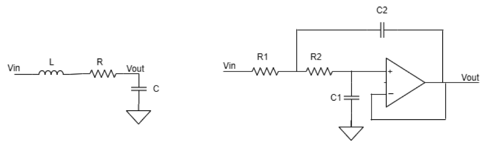
Fig. 1: Second-order LCR low pass filter and second-order active low pass filter.

RC low-pass filter
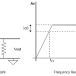
As shown below, a low-pass filter can be created by placing a resistor in series with the input signal and a capacitor in parallel with the input signal.

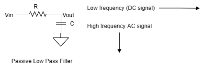
Fig. 2: Passive low pass filter Design

The cutoff frequency of the low-pass filter is given by
Fc = 1/2piRC
Fc – Cutoff frequency

               Pi – 3.141

For example:
R – 1K ; C – 10nF

I was doing math and calculating the cutoff frequency of the above values.
Fc = 1/2*3.141*1K*10nF    =  15.9 KHz

That means frequencies greater than 15.9 kHz will be attenuated, and frequencies below 15.9 kHz will be in the pass band.

LR low pass filter
LR low pass filter is composed of an inductor in series with the input signal and a resistor in parallel with the input signal and works the same as the RC low-pass filter; it attenuates the high-frequency band from a signal and attenuates more and more as the frequency increases.

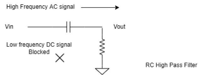
Fig. 3: Design of passive low pass filter

The LR filter circuit works on the principle of inductive reactance. That means how the resistance or impedance of the inductor behaves with frequency passing through it. Resistance has fixed resistance. But the inductor has different resistance for different frequency signals as capacitors do.

The inductor produces high impedance or resistance for high-frequency signals and very low resistance for low-frequency signals. It behaves just the opposite of a capacitor. Because of this, the resistor placement place is different in the RL circuit. The above circuit effectively blocks the high-frequency signal and passes the low-frequency signals.

The cutoff frequency is given by
Fc = R/2PiL

If  L =210mH & R = 10K in the above circuit,
then Fc will be  7.58KHz

That means if a complex signal is passed through the above filter, it will attenuate frequencies above 7.58KHz and let the below frequencies pass.

RC high-pass filter
A simple passive RC high-pass filter can be designed by using a capacitor in series with the input signal and a resistor in parallel with the input signal, as in the below circuit.

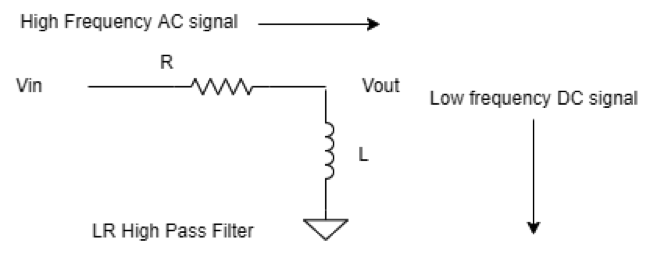
Fig. 4: Design of RC high pass filter

The capacitor is a reactive device that offers different resistance to signals with different frequencies interesting through the capacitor. A capacitor is a reactive device that offers very high resistance to a signal with a very low frequency or DC signal and low resistance to a very high-frequency signal. As a capacitor offers high resistance or impedance to a DC or low-frequency signal, it blocks them from entering through a capacitor.

The cutoff frequency of the RC high-pass filter is given by the formula given below.
Fc = 1/2PiRC

A high-pass filter is commonly used in various device circuits, like the microphone. As the microphone works on both AC and DC, it records the AC signals entering it and operates on the DC supply. Therefore, it becomes necessary to use it in the microphone recording circuit.

If, in the above RC high-pass filter     C = 10nF and R = 1K
Then    Fc = 1/2*3.14*1K*10nF
Fc = 15.923 KHz

The cutoff frequency is calculated at 15.923 kHz, meaning if a complex signal is passed through the above circuit, signals with a frequency below 15.923 kHz will be blocked, and frequency components above that will pass.

LR high pass filter
An LR high-pass filter can be composed of placing a resistor in series with an input source signal and an inductor in parallel with the input source signal entering in the circuit.

Fig. 5: Design of LR high pass filter

An inductor has inductive reactance that varies with different signals of frequencies and offers great resistance to high-frequency signals and very low resistance to low-frequency signals. It provides high resistance to high-frequency signals, so high-frequency current does not pass the inductor, and the signal chooses a low resistance path and travels to output. But low-frequency current faces very low resistance offered by the inductor, so it passes through the inductor to the ground.

The formula gives the cutoff frequency.
Fc = R/2PiL

For example, in the above circuit
R = 10K;        L = 470mH

Then the calculated cutoff frequency is
Fc = 3.39KHz

If a signal is passed through the above circuit, then frequency components of that signal below this frequency will be attenuated, and higher than this will be seen on the output.

You may also like:


  • Problems in filter implementation

  • What are the two types of hardware filters?

  • Types of filter responses

  • What are hardware filters and their types?

Filed Under: Featured Contributions, Hardware Filters, Tutorials


Next Article

← Previous Article
Next Article →

Questions related to this article?
👉Ask and discuss on EDAboard.com and Electro-Tech-Online.com forums.


Tell Us What You Think!! Cancel reply

You must be logged in to post a comment.

EE TECH TOOLBOX

“ee
Tech Toolbox: Internet of Things
Explore practical strategies for minimizing attack surfaces, managing memory efficiently, and securing firmware. Download now to ensure your IoT implementations remain secure, efficient, and future-ready.

EE Learning Center

EE Learning Center
“engineers
EXPAND YOUR KNOWLEDGE AND STAY CONNECTED
Get the latest info on technologies, tools and strategies for EE professionals.

HAVE A QUESTION?

Have a technical question about an article or other engineering questions? Check out our engineering forums EDABoard.com and Electro-Tech-Online.com where you can get those questions asked and answered by your peers!


RSS EDABOARD.com Discussions

  • RF-DC rectifier impedance matching
  • 12VAC to 12VDC 5A on 250ft 12AWG
  • Precision CAD Drafting Services for Architectural & Engineering Projects
  • SPI speed pic18f66j15
  • I/O constraint for Hold check

RSS Electro-Tech-Online.com Discussions

  • LED circuit for 1/6 scale diorama
  • stud mount Schottky diodes
  • Hi Guys
  • using a RTC in SF basic
  • Can I use this charger in every country?

Featured – Designing of Audio Amplifiers part 9 series

  • Basics of Audio Amplifier – 1/9
  • Designing 250 Milli Watt Audio Power Amplifier – 2/9
  • Designing 1 Watt Audio Power Amplifier – 3/9
  • Designing a Bass Boost Amplifier – 4/9
  • Designing a 6 Watt Car Audio Amplifier – 5/9
  • Design a low power amplifier for headphones- 6/9

Recent Articles

  • Fischer connector system adds ratchet locking system designed for 300g shock resistance
  • Littelfuse introduces tactile switch with enhanced bracket peg design for mounting strength
  • Infineon releases GaN switch with monolithic bidirectional design
  • Sienna Semiconductor data converters feature sample rates from 20 to 250 Msps
  • Delta’s 5,500 W power supplies achieve 97.5% energy efficiency for AI servers

EE ENGINEERING TRAINING DAYS

engineering

Submit a Guest Post

submit a guest post
Engineers Garage
  • Analog IC TIps
  • Connector Tips
  • Battery Power Tips
  • DesignFast
  • EDABoard Forums
  • EE World Online
  • Electro-Tech-Online Forums
  • EV Engineering
  • Microcontroller Tips
  • Power Electronic Tips
  • Sensor Tips
  • Test and Measurement Tips
  • 5G Technology World
  • Subscribe to our newsletter
  • About Us
  • Contact Us
  • Advertise

Copyright © 2025 WTWH Media LLC. All Rights Reserved. The material on this site may not be reproduced, distributed, transmitted, cached or otherwise used, except with the prior written permission of WTWH Media
Privacy Policy

Search Engineers Garage

  • Electronics Projects and Tutorials
    • Electronic Projects
      • Arduino Projects
      • AVR
      • Raspberry pi
      • ESP8266
      • BeagleBone
      • 8051 Microcontroller
      • ARM
      • PIC Microcontroller
      • STM32
    • Tutorials
      • Audio Electronics
      • Battery Management
      • Brainwave
      • Electric Vehicles
      • EMI/EMC/RFI
      • Hardware Filters
      • IoT tutorials
      • Power Tutorials
      • Python
      • Sensors
      • USB
      • VHDL
    • Circuit Design
    • Project Videos
    • Components
  • Articles
    • Tech Articles
    • Insight
    • Invention Stories
    • How to
    • What Is
  • News
    • Electronic Product News
    • Business News
    • Company/Start-up News
    • DIY Reviews
    • Guest Post
  • Forums
    • EDABoard.com
    • Electro-Tech-Online
    • EG Forum Archive
  • DigiKey Store
    • Cables, Wires
    • Connectors, Interconnect
    • Discrete
    • Electromechanical
    • Embedded Computers
    • Enclosures, Hardware, Office
    • Integrated Circuits (ICs)
    • Isolators
    • LED/Optoelectronics
    • Passive
    • Power, Circuit Protection
    • Programmers
    • RF, Wireless
    • Semiconductors
    • Sensors, Transducers
    • Test Products
    • Tools
  • Learn
    • eBooks/Tech Tips
    • Design Guides
    • Learning Center
    • Tech Toolboxes
    • Webinars & Digital Events
  • Resources
    • Digital Issues
    • EE Training Days
    • LEAP Awards
    • Podcasts
    • Webinars / Digital Events
    • White Papers
    • Engineering Diversity & Inclusion
    • DesignFast
  • Guest Post Guidelines
  • Advertise
  • Subscribe