The previous sections explained filters by their property, mathematical functions, time and frequency domain responses, and different types. Using the previous sections’ theoretical knowledge, we can implement it in the real world. However, that filter circuit won’t work according to your expectations.
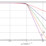
The figure below shows how the ideal and real filter work. The red dotted line represents the ideal low pass filter, and the blue line represents the real filter. According to the ideal filter curve, a frequency above 1 kHz should not pass. But in real life, it happens because the filter in doesn’t transient to cut off frequency sharply, as shown by the red dotted line. It happens as shown by the blue line.
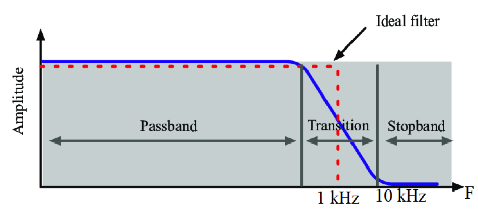
Figure 1: Cutoff frequency transition
Multiple sections of orders two and one are used to design a filter of higher order (mainly greater than two). In that case, each section’s frequency and quality factor should be the same. Otherwise, the overall response of the circuit will deviate from the desired response. This won’t be exact.
So in the typical engineering case, a tradeoff should be made that is exactly what the designers need and can vary from design to design. Designers need to ask themselves if their design must have the filter response or frequency exactly the same as they want, if the response can be accepted despite some ripple in the passband, and if the cutoff frequency deviates from the main frequency.
Some tradeoffs are intrinsic in the design of filters primarily because of the manufacturing of semiconductor components.
Passive components
The main problem is caused due to the resistor, capacitors, and inductors. As these components are available in standard values, the calculated value of capacitors, inductors, and resistors won’t be available commercially. However, they can be customized. Commercial passive components may not give the exact calculated value of passive components, but they can be used in parallel or series form. This will increase the cost and size of the design and parallelly increase the cost of manufacturing. Again, these components will have a tolerance of +-1 percent. Their dependency on temperature and current ratings will also affect their performance.
A practical way to save time and cost is using existing CAD programs for circuit analysis using standard values of passive components. Components drift can be analyzed over temperature, and a combination of series and parallel components can be analyzed to get the desired response within limits.
The calculated passive components’ values determine a filter’s cutoff frequency and quality factor. These passive components will drift the filter’s cutoff frequency and quality factor. This situation occurs in higher-order filters because they can roll off the gain after the cutoff frequency sharply compared to low-order filters. The forthcoming article “Practical implementation of filters” will give a practical example of a high-order filter.
The higher the quality factor, the more critical and precise value of components. A ratio of two or more components sets the quality factor, typically capacitors. In addition to the tolerance of components, the effect of temperature/time drift can also be added. Especially the capacitors, as they not only drift but also are a function of temperature.
While building the filter, there are infinite choices for selecting passive components value, but there is a limit in practical components size. Capacitor values between 20pF and 10uF are practical but not outside this range. For filter designing, electrolyte capacitors are not recommended due to their leaky property.
The same kind of problem occurs in certain resistors. Resistance values between 100 Ohm and 1 Mohm are recommended to design the filter. Resistance below 100 Ohm requires more current to get the drive and hence dissipates more power; in a filter design, these two situations should be avoided. Large resistance values are more prone to parasitics and can easily be coupled with small capacitance.
In electronics design, The performance of the circuit is affected by the layout design because it causes parasitic capacitances (unwanted capacitance inside the part of the electronic component) in the design. This can be formed between two traces of a PCB on the same layer or another side of the layer. Parasitic capacitances can be formed between adjacent component leads. As these capacitances are very small in value hence have a large effect in high-impedance nodes. This can be controlled by reducing the impedance of the circuit PCB. Remember that the effect of stray capacitances depends on frequency, and the effect increases with higher frequencies where the impedance drops.
Parasitics are not only associated with external sources but with components in themselves.
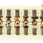
A capacitor is not just a capacitor. It has resistance and inductance in its lead wire, as shown in the figure below. In the capacitor specification, a resistance indicates leakage and poor power factor. In the filter design or any other circuit design, it is recommended to have a capacitor with low leakage and a good power factor. The best is polystyrene or Teflon film capacitor and metal resistor.
The below figure shows the metal film resistor and polystyrene capacitor.
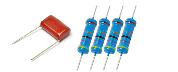
Figure 2: Polystyrene capacitor & metal film resistor
It is best practice to use surface mount components to reduce the parasitics of components. As leads of any components create inductance, SMD components are optimal for placement. The main disadvantage is that not all types of capacitors are available in SMD form. Ceramic capacitors are best for filter design, and the NPO family has the best characteristic. Ceramic capacitors are prone to microphonics and may act as motion sensors that can turn vibration into electrical sensors, which will be noise.
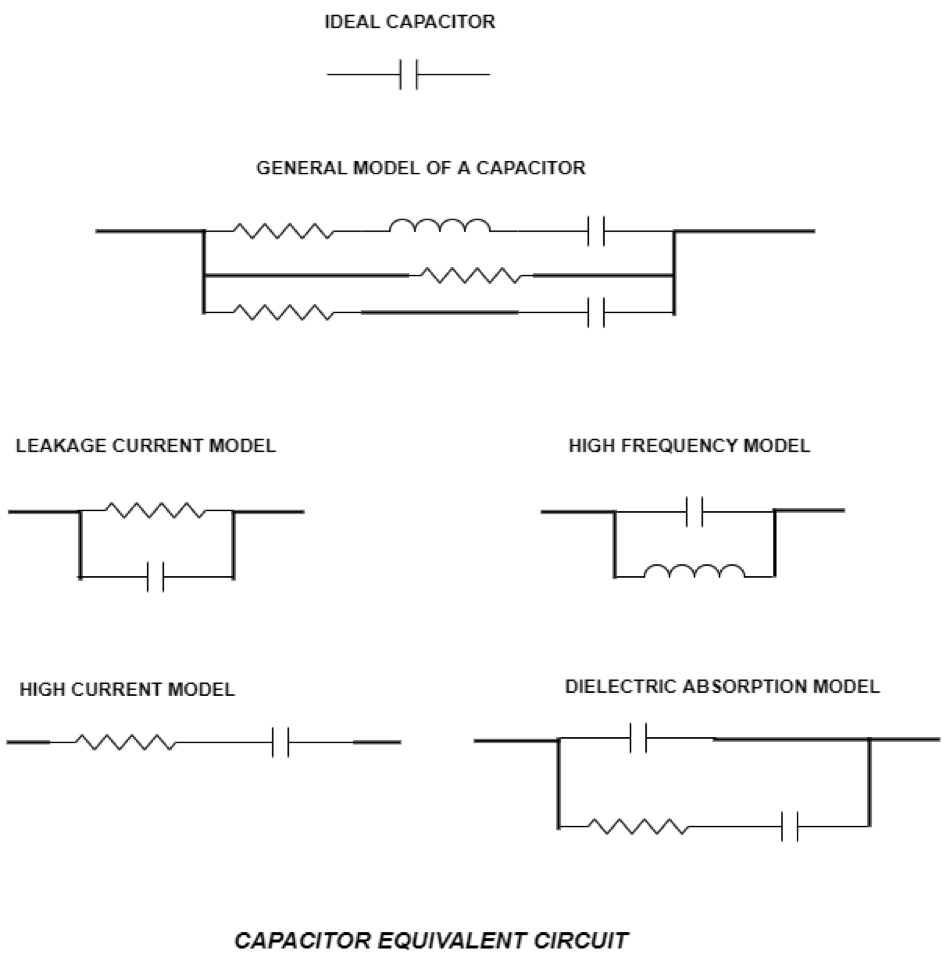
Fig. 3: Capacitor Equivalent Circuit
Due to leads, resistance also has parasitics inductance and parasitics capacitance.
Limitations of active components in filters
There are some properties of op amps that can best be used in filter design.
1. Infinite gain
2. Infinite input impedance
3. Zero output impedance
In the filter design, an opamp is used in designing active filters because of the below-explained properties of op amps:
Infinite gain (Ideal Case): Op amps have gain, so this component is best to use in a filter if you have a significantly less amplitude signal. Op amps gain can be added to the signal to amplify it.
Infinite Input Impedance (Ideal Case): Infinite input impedance (Ideal case) or High input impedance (Practical case) means the op amps input doesn’t require any current to feed the signal.
Zero Output Impedance (Ideal Case): Op amps have significantly less output impedance, which means they can give enough current to drive the connected circuit.
The above properties are only true for ideal op amps. Practical op amps always have high input impedance, near-zero output impedance, adjustable gain and don’t vary with frequency.
Amplifiers are constructed with the physical limitation of the devices, and due to this, they become band limited. And the main limitation of the op amp is its gain variation with the frequency. The gain should be of the first order for the stability of the op amp.
The op amp’s sullen-key configuration (a filter design topology of second order) is the least dependent on the frequency response of the op-amp. As the amplifier is used in gain block mode, it is required that the response should be flat to just past the frequency where the minimum attenuation starts.
Quality factor enhancement and peaking
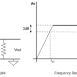
While designing the filter, it is necessary not to exceed the amplifier’s dynamic range. Peaking in the filter response may be caused by increasing the quality factor above 0.707. High-quality factors can cause an overload of the input and output.

Fig. 4: Effect of op amps frequency response on the quality factor.
The quality factor times the gain should also remain under the loop gain plus some margin. The effective quality factor decreases as soon as the amplifier overloads, and the transfer function changes even if the output seems undistorted. So it is clear that increasing the input level will change the transfer function.
These principles apply to all types of filters like low pass, high pass, bandpass, and band-reject filters. Enhancement in quality factor will not affect high pass filters since resonant frequency will be low in relation to the cutoff frequency.
You may also like:

Filed Under: Applications, Hardware Filters, Telecommunications, Tutorials, Wireless

Questions related to this article?
👉Ask and discuss on Electro-Tech-Online.com and EDAboard.com forums.
Tell Us What You Think!!
You must be logged in to post a comment.