Even though the microcontrollers are purely digital devices which work on logic0 and logic1 voltages they are commonly found interfaced with analog system or circuits. The microcontroller can read the analog input voltage by sampling it and converting it to their digital values with the help of Analog to Digital Converter (ADC). The microcontroller can also generate an analog voltage on any external device with the help of Pulse Width Modulated (PWM) waves. Most of the microcontrollers have built-in PWM module and ADC modules which helps them in reading analog voltage inputs and generating analog voltage outputs on an external device. Those who have done some basic experiments with the PWM and ADC modules know how complex it is to get them configured, initialized and make them work properly together. All those things are simplified in an arduino board in such a way that even a beginner can quickly interface it with analog input and output devices. The arduino can be used as a stand-alone board of which the output or inputs can be taken from the boards or given to the board using convenient connectors. Both digital and analog inputs and outputs are available in all arduino boards. The arduino boards can communicate with other devices using digital input/output analog input/output standard communication ports like USART, IIC, and USB etc.
In this project the arduino pro-mini board is used which is programmed with the help of arduino IDE version 1.0.3 on windows operating system.

Fig. 2: Typical Arduino Pro-Mini Board

Fig. 3: Arduino IDE Software Window
Another hardware which can perform the USB to TTL conversion is used to upload the program into the arduino board.

Fig. 4: External USB to TTL converter board for programming Arduino and serial communication
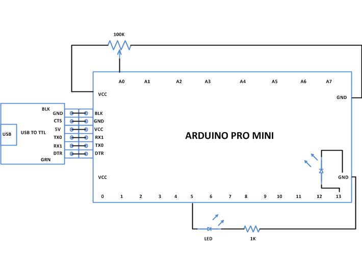
It is assumed that the reader has gone through the project how to get started with arduino and done all the things discussed in it. The arduino pro-mini board can have a maximum of eight analog pins which can be configured as analog input pins. The pins are marked in the board as A0, A1, A2, … A7. They are actually the input channels to the built-in ADC which can read the analog value and convert them to the digital equivalent. Some pro-mini boards have lesser number of analog pins. In this particular project analog pin 0 and analog pin 1 are using only one of them as analog input and the other as analog output. The variable pin of a potentiometer is connected to the analog pin;in this project the pin A0. The other two pins of the potentiometer is connected to the VCC and GND so that as the variable moves it can divide the entire supply voltage and provide it as the analog input voltage for the arduino board.
The arduino pro-mini board normally has six analog output pins which can be used to generate analog output voltage. The pins marked in the board as 3, 5, 6, 9, 10, and 11 can act as the analog output. They are actually the output channels to the built-in PWM module which can generate the analog output voltages. An LED is connected to the analog output pin through a current limiting resistor; in this project it is connected to the pin 5. The code continuously reads the value from the potentiometer and writes the corresponding value to change the brightness of the LED connected to the pin 5.
THE CODE
constintanalogInPin = A0; // Analog input pin that the potentiometer is attached to
constintanalogOutPin = 5; // Analog output pin that the LED is attached to
intpotvalue = 0;
intoutputvalue=0;
void setup()
{
;
}
void loop()
{
// read the analog in value:
potvalue = analogRead(analogInPin);
// map it to the range of the analog out:
outputvalue = map(potvalue, 0, 1023, 0, 255);
// change the analog out value:
analogWrite(analogOutPin, outputvalue);
// wait 2 milliseconds before the next loop
// for the analog-to-digital converter to settle
// after the last reading:
delay(2);
}
The details of the function setup(), loop() are already explained in the project how to get started with the arduino. The details of the other basic functions like delay() are explained separately in the project how to use digital input and digital output of arduino. There are functions in the above code which can perform analog read and analog write namely analogRead() andanalogWrite() respectievely. The details of the functions are discussed in the following section.
analogRead()
This function can read an analog value from an analog pin mentioned in its argument and can returns that value. Suppose if there is a variable ‘var’ into which the vlue of the analog pin A0 is need to be read into, one can use the analogRead() function as shown below;
var = analogRead(A0);
The above statement will enable the built-in ADC of the arduino’s microcontroller which then converts the analog value to its 10 bit digital equivalent and then stores in the variable ‘var’. The variable ‘var’ is expected to be of the type integer.
analogWrite()
This function can write an analog value into an analog output pin mentioned in its argument to generate the equivalent voltage on that pin. For example one can make use of the analogWrite() function to generate a voltage equivalent of value 100 on an analog output pin 5 as shown below;
analogWrite(5, 100);
The above statement will actually write the value 100 to an 8 bit PWM module which will generate a corresponding width modulated waveform on the pin number 5 so as to generate the equivalent voltage on the device connected to that pin.
map()
The map() is a built-in function which can be used to map the value from one rage to another range. For example the ADC of the arduino generates 10 bit values but the PWM module of the arduino can produce 8 bit equivalent waveforms. If there is a requirement to directly write the analog input value to the analog output one can make use of the map() function as follows;
var = map(potvalue, 0, 1023, 0, 255);
The above statement will convert the value which is in the range of 0 to 1023 (the output of 10 bit ADC) into the range 0 to 255 (the input range of 8 bit PWM) and stores it in a variable ‘var’. The variable ‘var’ could be of the type integer or character.
Now once the coding is finished one can verify and upload the code to the arduino board as explained in the project Getting started with Arduino and the brightness of the LED can be observed to vary as the variable of the potentiometer moves.
You may also like:


Project Source Code
###


/*============================ EG LABS ===================================//


 Demonstration on how to use analog input and output of an arduino board


 The circuit:

 * Potentiometer attached to analog input A0

 * one side pin (either one) to ground

 * the other side pin to +5V

 * LED anode (long leg) attached to digital output 5

 * LED cathode (short leg) attached to ground through a 1K resistor


//============================ EG LABS ===================================*/


const int analogInPin = A0;  // Analog input pin that the potentiometer is attached to

const int analogOutPin = 5;  // Analog output pin that the LED is attached to

int potvalue = 0;

int outputvalue=0;


void setup()

{

  ;

}


void loop()

{

  // read the analog in value:

  potvalue = analogRead(analogInPin);

 // map it to the range of the analog out:

  outputvalue = map(potvalue, 0, 1023, 0, 255);

  // change the analog out value:

  analogWrite(analogOutPin, outputvalue);

  // wait 2 milliseconds before the next loop

  // for the analog-to-digital converter to settle

  // after the last reading:

  delay(2);

}

###
Circuit Diagrams
Project Components
Project Video
Filed Under: Arduino, Electronic Projects
Filed Under: Arduino, Electronic Projects

Questions related to this article?
👉Ask and discuss on Electro-Tech-Online.com and EDAboard.com forums.
Tell Us What You Think!!
You must be logged in to post a comment.