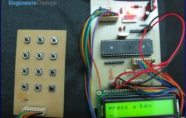
Keypad is most widely used input device to provide input from the outside world to the microcontroller. The keypad makes an application more users interactive. [[wysiwyg_imageupload::]]The concept of interfacing a keypad with the ATmega16 is similar to interfacing it with any other microcontroller. The article of Interfacing keypad with 8051 can be referred for detailed description of the methodology used here. This article explains the interfacing of a 4×3 keypad with AVR microcontroller(ATmega16) and displaying the output on a LCD. The algorithm and detailed explanation for keypad interfacing is given in above mentioned article. The brief steps to interface the keypad with AVR are written below:1. Configure the row pins or column pins.2. Make all output pins to low and input pins to high.3. Keep monitoring the port value, where the key pad is connected.
How to interface LED with AVR Microcontroller (ATmega16)- (Part 4/46)
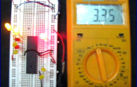
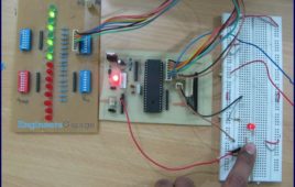
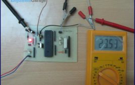
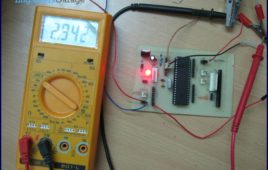
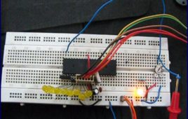
ATmega16 has 32 I/O pins to communicate with external devices. Before interfacing with external devices, these pins must be cofigured as input or output pin. [[wysiwyg_imageupload::]]This article demonstrates the basic I/O operation of ATmega 16 using LEDs. All the four ports can be configured to read an input from some external device or to give output to any external device as per the application. For e.g., a switch is connected to a particular pin, that pin should be configured as input to read the values from the switch (external Device in this case) and if you are connecting a LED to any pin of the port then that particular pin should be configured as output to transmit the signal to the LED (external device in this case). A single port can be configured such that some of the pins of the same port are input and some are output. Read on more to understand how LED interfacing is done with the help of an AVR.
AVR Microcontroller : All You Need To Know- (Part 1/46)
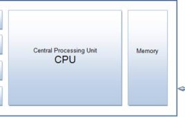
There are number of popular families of microcontrollers which are used in different applications as per their capability and feasibility to perform the desired task, most common of these are 8051, AVR and PIC microcontrollers. This article introduces the AVR family of microcontrollers.AVR was developed in the year 1996 by Atmel Corporation. AVR is an 8-bit microcontroller belonging to the family of Reduced Instruction Set Computer (RISC). In RISC architecture the instruction set of the computer are not only fewer in number but also simpler and faster in operation.
How to use External (Hardware) Interrupts of AVR Microcontroller (ATmega16)- (Part 22/46)
When an interrupt occurs, the normal flow of instructions is suspended by the microcontroller and the code corresponding to the interrupt, which has occurred, is executed. Once the code corresponding to the interrupt is executed completely the execution again begins from the same instruction where it was stopped. Following is what happens when an interrupt…
Waveform Generation using AVR Microcontroller (Atmega16) Timers- (Part 16/46)

At times we come across applications or situations wherein we need to generate square waves with the microcontroller. The square wave can be generated by [[wysiwyg_imageupload::]]programming a pin which toggles between 0 and 1 with a certain time delay. Alternatively, the inbuilt feature of AVR timers can be used in square wave generation. The advantage of using AVR timers in wave form generation is that the output pin toggles automatically when the timer condition are fulfilled. This article focuses on usage of AVR timer for simple square wave generation. It is better to use CTC mode instead of Normal mode because in CTC mode, frequency can be easily adjusted. ?When the Timer is triggered, register TCNTn counts the value constantly as timer started. Each timer has an OCRn (Output Compare Register), which is continuously compared with TCNTn register. In CTC mode whenever match occurs, OCFn (Output Compare Flag) will set to 1. If continuous wave form generation is required, OCFn must be reset again. Alternatively, if OCIEn (Output Compare interrupt) and Global interrupt flags in SREG are set, OCFn will reset automatically after interrupt execution.
Phase Correct PWM (Pulse Width Modulation) Mode of AVR microcontroller Timer- (Part 17/46)
Pulse Width Modulation is well known technique for controlling power electronics devices like SCR, IGBT etc. PWM is also used in motor speed controlling.[[wysiwyg_imageupload::]] Square wave generation by using AVR timers is explained in previous article. The AVR timers have feature of PWM wave generation as well .This article describes PWM generation capability of AVR timers. There are four in-built PWM channels in ATmega16. The PWM outputs are received on pins OC0, OC1A, OC1B and OC2. Readers can refer the previous article which gives explanation of these pins. The Phase correct PWM mode can be selected by assigning bits WGM0[1:0]=01. This mode is based on dual slope operation. In dual slope operation, TCNTn counts from bottom value to maximum value and maximum value to bottom value. The OCRn register compares the value with the TCNTn register constantly during up-counting and down-counting. On compare match PWM output pin (OCn) behaves according to inverting or non-inverting mode which can be selected by programming of COMn [1:0] bits.
How to use fast PWM (Pulse Width Modulation) Mode of AVR microcontroller Timer- (Part 18/46)
This article is in continuation of PWM generation using AVR timer. In the previous article, PWM generation using Phase correct PWM mode is described. [[wysiwyg_imageupload::]]However, there are some applications like DAC, power regulation and rectification etc. which require high frequency PWM wave. The PWM generation using Fast PWM mode is suitable for such applications. This article focuses on Fast PWM mode of AVR Timer. The Fast PWM mode is based on single-slope operation. In single slope operation, the register TCNTn counts from bottom value to maximum value and its value resets to zero. The counting starts again from bottom. The register OCRn compares the value with the TCNTn register constantly. If the timer is configured in non-inverting mode, PWM output pin (OCn) goes low when the value of the above two registers matches. The OCn pin becomes high when the TCNTn register reaches at bottom value. In inverting mode OCn pin behaves opposite to non-inverting mode. For timer 0 fast PWM mode, following table shows the functionality of COM 0[1:0] bits.
SPI (serial peripheral interface) using AVR microcontroller (ATmega16)- (Part 37/46)

There are different protocols for serial communication between two deceives like, USART, SPI, I2C etc. Before selecting any communication protocol, data transfer [[wysiwyg_imageupload::]]rate is an important parameter. SPI transfers data at high speed data. AVR microcontroller contains on chip SPI interface. This article will explore the hardware configuration and programming of SPI. Serial Peripheral Interface is a synchronous, full-duplex protocol. SPI is also known as “3-wire interface” protocol because it needs 3 communication lines named MISO, MOSI and SCK. SPI protocol needs two devices for communication. One of them is considered as a MASTER and another one as a SLAVE.AVR microcontrollers contain both MASTER and SLAVE interface on single chip. Thus, a microcontroller can work as both master and slave device. The SPI is synchronous data transfer protocol, so clock pulse is needed to synchronize both master and slave device. The clock pulse is generated from master side. The SCK pin of master provides clock pulse to slave device.
How to disable JTAG of AVR microcontroller- (Part 24/46)
JTAG stands for “Joint Test Action Group” which was standardized as the IEEE 1149.1 Standard Test Access Port and Boundary-Scan Architecture in 1990. JTAG [[wysiwyg_imageupload::]]is generally used in IC debugging and device programming. Atmega16 consists of one JTAG port which shares four pins with PORTC. Until JTAG port is not disabled, these pins can’t be used as normal I/O pins. This article explores the methods for JTAG disabling. JTAG interface shares PC2, PC3, PC4 and PC5 of ATmega16. To use these four pins for general I/O operations, JTAG must be disabled. There are two methods for disabling JTAG: 1. By programming2. Using AvrdudeThere is a register in atmega16 MCUCSR (MCU control and status register). It consists of JTD (JTAG disable) bit as 7th bit of register. JTAG can be disabled by writing 1 to this bit.JTAG can be permanently disabled by configuring two fuse bits, OCDEN and JTAGEN (must be disabled). This is done by using Avrdude software.
How to use inbuilt analog comparator of AVR microcontroller- (Part 29/46)

Analog comparator is a device which compares two input voltages and generates output accordingly. The article on IR sensor explains the use of comparator in [[wysiwyg_imageupload::]]sensor designing. Comparators form an integral part of circuit designing in majority of the applications. AVR microcontrollers have in-built analog comparator. Using the in-built analog comparator of AVR, the controller can be used to compare the signal and process the signal as well. This reduces the external comparator components on our circuits. In this article proximity sensor is designed using in-built analog comparator of ATmega16. The analog comparator needs two inputs positive and negative. The positive input is given on AIN0 (PB2) pin of controller. In ATmega16 nine pins are available to connect negative input of comparator. This means microcontroller can compare maximum of nine analog signals with one positive input voltage. Although, signals are not compared simultaneously but the time difference between two consecutive comparisons is of the order of microseconds which is quite low to identify. The negative input of comparator is applied on pin AIN1 (PB3).
How to use internal ADC of AVR microcontroller using interrupts- (Part 28/46)
This article is in continuation to AVR interrupts. There are two types of interrupts external and internal in AVR microcontroller. The aforesaid article covers [[wysiwyg_imageupload::]]external interrupts. AVR microcontrollers have seventeen internal interrupts. These internal interrupts are generated by the internal peripherals of Microcontroller like Timer, ADC etc. The internal interrupts are used for efficient operation of the internal peripherals. This article explains the internal interrupts using the example of an ADC interrupt. Each internal peripheral system consists of one IE (interrupt Enable) bit which activates the internal interrupts of that peripheral. For example, in-built ADC of AVR consists of ADIE (ADC interrupt Enable) bit in ADCSRA register.In addition, the I-bit of SREG is also activated to activate interrupts. SREG is a status register of AVR microcontroller which contains information about the result of most recently executed arithmetic instructions.
RFID interfacing with AVR microcontroller (ATmega16) using interrupts- (Part 40/46)
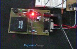
This article covers how to extract and display the twelve byte unique tag ID received by RFID module on LCD using interrupt method. Before proceeding to this [[wysiwyg_imageupload::]]article readers must have knowledge of serial interrupt and LCD. In the previous article of RFID, polling method was used where the microcontroller was continuously monitoring the RXC flag. Keeping the microcontroller busy in monitoring the flag is not a good programming technique, so instead of polling method a programmer should prefer using interrupts. Since the output data of the RFID module uses RS232 protocol and is serial in nature, serial interrupt is used to receive the twelve byte unique ID. Whenever an RFID tag comes in the proximity of the RFID reader module, the module transmits the twelve byte unique ID. Every time one byte of data is received, the controller is interrupted and the corresponding ISR gets executed, which stores the byte in a temporary variable and sends it to the LCD for display.
How to interface RFID with AVR microcontroller (ATmega16)- (Part 39/46)

Knowingly or unknowingly the RFID technology is used by us in our day to day life. The most familiar example is seen in MNCs, schools and offices for daily [[wysiwyg_imageupload::]]attendance or automatic door opening system. The RFID contains two parts, namely, tag and receiver modem. When an RFID tag comes in the range of receiver, the tag gets activated and transmits its unique identification code to the receiver module.The output of the RFID receiver is the unique ID in either serial (RS232) or wiegand format. Most of the receivers are equipped with additional hardware to send the extracted code in the above format, which can then be used by digital signal processors. This article shows the interfacing of ATmega16 with RFID. The RFID module used here gives a 12 byte unique ID of a particular tag in serial RS232 logic level format. Hence a level converter MAX232 is used in between RFID receiver module and microcontroller. The connections of RFID module and ATmega16 are shown in the circuit diagram.
Serial communication with AVR microcontroller using interrupts- (Part 23/46)
In our previous articles on serial data transmission using AVR microcontroller we have demonstrated serial communication using the polling method. In Polling, [[wysiwyg_imageupload::]]the microcontroller waits for the RXC flag (in the case of serial receiver) to go high and then moves to the next instruction. This is not a good programming technique to keep the microcontroller busy to monitor the RXC flag. Alternatively, serial interrupts can be used to transmit and receive data. This increases the efficiency of the code and keeps the processor free for other tasks. The article explains serial data reception using interrupts concepts. It is recommended that the readers should study the article on AVR Interrupts before proceeding. The UCSRB register has RXCIE (Reception Complete Interrupt Enable) bit, which is used to enable the serial reception interrupt. The I-bit of SREG register is must be set to enable global interrupt of ATmega16. The circuit diagram is same as used in previous article of USART.
How to interface AVR microcontroller with PC using USART (RS232 protocol)- (Part 13/46)

This article covers data transmission using 8 bit USART. The readers should have a basic understanding of serial communication and how to receive the serial [[wysiwyg_imageupload::]]data output. More details on these topics are available on Serial communication using AVR Microcontroller USART. The registers of USART system are already explained in previous article. Before transmitting the data, it must be stored in UDR register. The HyperTerminal software is used to show received data. A sequential process can be followed to transmit the data to COM port of computer. Continue reading to find out how interfacing and transmission through 8 bit USART can be done with the help of AVR microcontroller.
Serial communication (Data receive) using AVR Microcontroller (ATmega16) USART- (Part 12/46)
Communication between two entities is important for the information flow to take place. In general the information transport system can be parallel in which the [[wysiwyg_imageupload::]]complete byte of data is sent at a time, with each bit having a separate dedicated line or it can be serial where only one communication line is available which is shared by all the bits sequentially. The pros and cons of these two systems are equivalent and selection between the two depends on the application.Data can be exchanged using parallel or serial techniques. Setup for parallel data transfer is not cost effective but is a very fast method of communication. Serial communication is cost effective because it requires only a single line of connection but on the other hand is a slow process in comparison to parallel communication. This article explains serial communication of AVR microcontroller (ATmega16) with PC. The data is transmitted from the controller using RS232 standard and displayed on the PC using Hyper Terminal.
How to use inbuilt ADC of AVR microcontroller (ATmega16)- (Part 26/46)
Microcontroller understands only digital language. However, the inputs available from the environment to the microcontroller are mostly analog in nature, i.e., they [[wysiwyg_imageupload::]]vary continuously with time. In order to understand the inputs by the digital processor, a device called Analog to Digital Converter (ADC) is used. As the name suggests this peripheral gathers the analog information supplied from the environment and converts it to the controller understandable digital format, microcontroller then processes the information and provides the desired result at the output end. ATmega16 has an inbuilt 10 bit, 8-channel ADC system. Some of the basic features of Armega16 ADC are:· 8 Channels.· 10-bit Resolution.· Input voltage range of 0 to Vcc.· Selectable 2.56V of internal Reference voltage source.· AREF pin for External Reference voltage.· ADC Conversion Complete Interrupt.
Display custom characters on LCD using AVR Microcontroller (ATmega16)- (Part 9/46)

This is the most interesting article to play with LCD. After going through the article, you can create any character/symbol which cannot be created using the [[wysiwyg_imageupload::]]ASCII values for example smiley. You can even create small games. Conventionally 16X2 LCD is use to display text or numerical values. It is possible to display special characters, your own designed characters too on LCD by using its 5 x 8 matrix block. These special characters are stored in the CGRAM of LCD. This article shows how to create and display special character on LCD using ATmega16. For more details refer to the article how to create custom characters. This article assumes that the readers are aware of the concepts of interfacing LCD with AVR microcontroller (ATMEGA 16). For more information about interfacing LCD with AVR, refer How to display string on LCD using AVR. In order to create a custom character its configuration is first defined in the CGRAM of the LCD. A maximum of eight characters can be stored at a time in the 16 x 2 LCD.
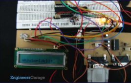
How to display text on 16×2 LCD using AVR microcontroller (ATmega16)- (Part 8/46)
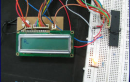
This article is in continuation to the article Single character LCD display using AVR. The aforesaid article shows how to display a single letter on LCD. Moving [[wysiwyg_imageupload::]]forward towards learning to work with LCD, this article explains how to display a string on LCD. Displaying string is occasionally used in many applications. The connection of the LCD with the AVR microcontroller (ATmega16) is shown in the circuit diagram. A string is nothing but a sequence of characters. The following steps explain how to display a string on the LCD. Keep on reading to find out How to code and interface in order to display text on 16×2 LCD using AVR microcontroller (ATmega16).
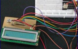
How to interface 16×2 LCD with AVR microcontroller (ATmega16)- (Part 7/46)
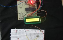
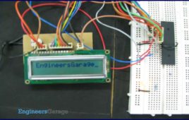
LCD is used to present textual information to the users. It is great fun to work with LCD. Also LCD makes your application more interactive. LCD comes in various [[wysiwyg_imageupload::]]configurations and the most popular one is 16×2 matrix display. This article shows the interfacing of ATmega16 with LCD by displaying a simple character on the LCD. For more information about LCD, refer the article LCD interfacing. In this project LCD is working in 8-bit mode i.e., the data transferred to the LCD must be in 8-bit data form. The PortA of ATmega16 is connected to data pins of LCD and is defined as LCD_DATA. PortB is defined as control pins (Rs, R/W and En). Conceptually, interfacing LCD with AVR microcontroller is similar to that of interfacing it with any other microcontroller. Continue reading to understand interfacing circuitry and coding concepts of the project.