
Any microcontroller based system typically has an input and a corresponding output. Taking simple output with a PIC microcontroller has been explained inLED [[wysiwyg_imageupload::]]blinking with PIC18F4550. This article explains how to provide an input to the controller and get a corresponding output using PIC18F4550. PIC18F4550 has a total of 35 I/O (input-output) pins which are distributed among 5 Ports. Each Port of a PIC microcontroller corresponds to three 8-bit registers (TRIS, PORT & LAT) which should be configured to use the Port for general I/O purpose. For more details, refer LED blinking using PIC.To configure a particular port/pin as input, the corresponding TRIS register/TRIS bit should be set to high (1). For output, the relevant TRIS register/bit should be set to low (0). Read on to know more about PIC micro controller and get a step by step approach to take input with PIC. A must learn for every budding PIC enthusiast.
How to interface Seven Segment Display with PIC18F4550 Microcontroller- (Part 3/25)

A typical seven-segment consists of 8 LEDs arranged in a pattern to display values. A seven-segment can be either of the two types, namely, Common Anode (CA) and Common Cathode (CC). For more details, refer Seven segments. A single seven-segment requires a minimum of 7 data pins of controller to display different values. The connections…
How to interface LEDs with PIC Microcontroller (PIC18F4550)- (Part 1/25)

It is necessary to understand basic I/O operations of PIC18F4550 before dealing with its complexities. This article presents a way to take simple output from a PIC [[wysiwyg_imageupload::]]microcontroller. This learning would also help in interfacing of external devices with the controller. Here the output from the microcontroller is taken on a set of LEDs which are made to blink in an alternate fashion. PIC18F4550 has a total of 35 I/O (input-output) pins which are distributed among 5 Ports. As opposed to a basic 8051 microcontroller like AT89C51 which has most of the port pins serving single function, the port pins of a PIC microcontroller are multiplexed to serve more than one purpose. The 35 I/O pins of PIC18F4550 are also multiplexed with one or more alternative functions of controller’s various peripherals. Each Port of a PIC microcontroller corresponds to three 8-bit registers which should be configured to use the Port for general I/O purpose.
Remote DC Motor controller with Digital Display
This is bit little extension to previous 89C51 based DC motor controller. A digital speed indicator (seven segment displays) are connected to show speed variation. All other things remains same NOT gates, DC driver etc. Operation of 89C51 also changes as it will now work as serial data receiver. I suggest you if you do…
Multi Digit Wireless Password Lock with LCD
This is a complete different application from any other applications you have seen till yet. With this unit you can activate or deactivate any application/device with the use of password only. Means to activate any device/application first you need to enter correct password. If you don’t device won’t be activated. you must have seen such…
AC Voltmeter with Digital Display
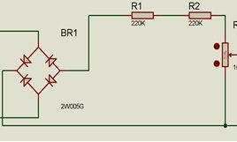
In Electronic field voltmeters have found an essential place, Voltmeters are of two types AC &DC and here I have demonstrated a working AC Voltmeter. It has a large range from 0V to 1000V.The output is shown on 7 segment display.The main part of this project are :- Converting Circuit(For converting Ac to dc in range of 0-5V), ADC Interfacing(10 bit Inbuilt ADC of 16F676), 7 Segment Multiplexing.I have used PIC 16f676 microcontroller in this circuit. It has bridge rectifier which is made from diodes In4007.It convert Ac Voltage to Dc Voltage. Next is Voltage divider circuit which converts any voltage from 0 to 1000v to 0 to 5v range. It is made using two resistors and a potential meter in series. Next capacitor is used for removing ripples .the zener 5.1V is used for protection it will never give voltage to controller more than 5.1 V.