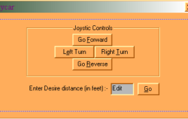
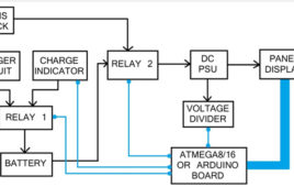
This is somewhat similar application that you have seen in “Remote controlled robo-vehicle”. The main difference is that now instead of remote now the computer will generate controlling signals through software written in VC++ which will be transmitted through RF transmitter attached to LPT port. Here again the term robo vehicle means a vehicle that can move in…
Industrial Laser cutting machine
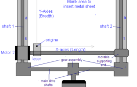
Laser is used to cut different metal sheets, glass, diamond and all other very hard things as this becomes very easy to cut using laser rather than using different blades. It’s one kind of CNC machine in which two stepper motors displaces the laser to calibrated distance. As one enters the dimension of plate (L X B) the…
Load Positioning System
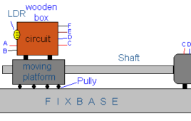
Sometimes it is needed that the object should remain inline or in contact with other moving object. For example in satellite tracking system the dish antenna should always point to moving satellite to receive maximum signal. a slight deviation may also reduce the signal strength. In gun barrel position system for military tank or anti-aircraft gun once the target is…
Liquid level Controller

Keeping the liquid up to certain level in tank is one of the widely used applications in petroleum and consumable goods producing industries. Certain amount of liquid should be always there in the tank to keep the liquid pressure as it is. To maintain this level there is a need of liquid level controller. It’s…
Traffic Control System
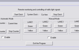
Actually this is remote traffic monitoring and control system in which a police man can control the flow of traffic from a remote location through his computer. He can generate all three traffic signals (red, green & yellow) on a click of mouse only. Also he can divert the flow of traffic by monitoring it…
CD 4013 Based Two Way Switch
In festival days, we switch ON the lights of our corridor, balconies or staircase. In the case when people have lighting done at two different locations, they have [[wysiwyg_imageupload::]]to go to two different places to switch ON the light but, with the help of this circuit, you can switch ON both the lights with a simple touch. This simple circuit is built around CD4013 which has two independent flip flops on a single chip and each module is further equipped with a group of pin outs assigned as data, set, reset, clock input and a couple complementary output Q and NOT Q. CD4013 is a 14 pin IC which contains two independent sets of flip flops and in our circuit we are utilizing both. Read on more to find out how the circuit is made and how it works.
Flip Flop based Staircase Switch
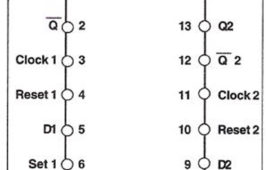
In many cases, the stairs have a power switch at the bottom which is often left switched on during night. No one wants to go down to switch it off and hence, [[wysiwyg_imageupload::]]unnecessary on, it leads to wastage of electricity.To solve this problem we have described a simple circuit which contains two micro switches; one at the top and other located at the bottom of the staircase that can be pushed and released easily during climb-up from the bottom of the staircase or climb-down from the top of staircase. In short you can use any switch to on and off the light.This simple circuit is built around a CD4013 IC which has two independent D type flip flops which exist in complimentary states and can store information. Each module is further equipped with a group of pin outs assigned as data, set, reset, clock input and a couple complementary output Q and Not Q.
CD 4013 based Sound Sensing Module

In this circuit when you clap or whistle in front of a Mic, a flower connected in the output starts rotating. For making this circuit, we have used CD4013 IC, DC [[wysiwyg_imageupload::]]motor and few more components. IC CD4013 contains two independent D type flip flop which exist in one of two states and can store information. Each module is further equipped with a group of pin outs assigned as data, set, reset, clock input and a couple of complementary outputs Q and . As we know, it has couple of output that change or toggle state as response to trigger applied to input terminals. To put in simple words, this circuit describes movement of a DC motor based on the voice sensing capabilities provided to it through a microphone. The DC motor can be accessorized using a variety of attachments such a miniature flower (in this case), a small fan etc.
CD 4060IC based Message Display Circuit
This simple message display can be used to display any message such as warnings, wishes, address notifications etc. as it will automatically turn ON at night or in [[wysiwyg_imageupload::]]dark. This circuit is based on CD4060 IC, LDR and few more components so that we can be easily made and can be gifted to friends. Here total of 12 bright LED glow inside the four segments (I through IV as shown in fig below) of the message plate to display different message. We can use bright white LED’s or different color LED’s to indicate different words. In this circuit, different segments glow for different duration of time. IC CD4060 is 14 stage ripple carry binary counter, divider and an oscillator. Its built in oscillator is main feature of this IC, so it can be used in numerous applications like flasher, clock generator in timer circuits. The resistance of LDR is very high in darkness, which reduces to minimum when LDR is in light.
CD4049 Based LED torch
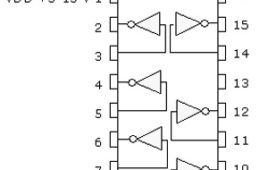
A simple LED torch would light up 3 white LED from 6 volts supply in case of emergency or in darkness. It is quite light-weight and handy, thus, can be used [[wysiwyg_imageupload::]]while traveling in train or in bus. Here we have used CD4049 IC which is a hex inverting buffer CMOS chipCD4049 contains six inverter gates in one package as shown in diagram. In this, pin 3 is input and 2 is for output. For first gate similarly pin 5 is input and pin 4 is output for second gate similarly we have four more gates. Pin1 1 is for supply voltage and pin 8 is connected to ground. Pin 13 and 16 are unused. The circuit is based on NOT gate CD4049 IC and utilizing 3 gates of NOT gate IC.
Voltage Doubler Circuit Using IC 4049
The circuit described here would produce an output voltage having twice the magnitude of the input voltage. In this circuit, we are using 6 Volts as input supply [[wysiwyg_imageupload::]]and we are getting 12 volts as its output. It is based on the popularly used hex inverter CD4049 IC. This can be made with the help of single IC with few more components.CD4049 contains six inverter gates in one package as shown in diagram. In this, pin 3 is input and 2 is for output. For first gate similarly pin 5 is input and pin 4 is output for second gate similarly we have four more gates. Pin1 1 is for supply voltage and pin 8 is connected to ground. Pin 13 and 16 are unused.
Magic Eye Circuit Using 4049 IC
Magic eye can be used as automatic guest indicator in your home. Just install this at the bottom of the door and whenever a person would arrive, his shadow will [[wysiwyg_imageupload::]]fall on the circuit giving an indication that somebody is present on the door without the knowledge of the visitor. It can also used as a prevention measure against vandalism. So, apart from homes, it can also be used shop and banks. This circuit is based on popularly known hexa inverter IC CD4011, LDR and a few more components. The circuit is based on NOT gate CD4049 IC. In NOT gate, we will get output as logic high when logic zero is provided and we will get logic zero when logic1 is provided in input. Keep on reading to find out how the circuit is constructed and how it works.
Timer Circuit using IC CD 4060
Several times we forget to switch off the gas, electric oven, stove or motor while watching TV or taking on the phone or while talking to a friend in your [[wysiwyg_imageupload::]]neighborhood. To solve this problem we have described a circuit below which gives an alarm after the preset time interval selected by you. In this you can select 7 different time intervals with the help of a rotary switch. Therefore after a preset interval of time it will give a loud alarm and reminds you that you have to off your machine or gas.The timer circuit is built around the CD4060 which is 14 stage ripple carry binary counter, divider and an oscillator. Its built in oscillator is main feature of this IC that’s why it can be used in numerous application like flasher, clock generator in timer circuits.
Electronic Timer Circuit
Nowadays students are required to answer a set of question in a given time of 15 minutes, 30 minutes or an hour. Hence the circuit describe below can be used [[wysiwyg_imageupload::]]by the student as a clock while they are preparing for the competitive exams.It will give them audio visual sound after the pre set time interval. In our circuit it is 15 minutes hence it will give an alarm after every 15 minutes. The timer could be programmed for other periods as well. By calibrating the variable resistor by some hit and trial method, you can vary the time period. We have also provided a reset switch so that you can reset it when you are required to start it again. The circuit is built around CD4060 and few more components. IC CD4060 is 14 stage ripple carry binary counter, divider and an oscillator.
Multi Color Lighting
The multi color lighting circuit describe below can be used to decorate your house or your temple with light of different colors and this will not use electricity [[wysiwyg_imageupload::]]but solar energy. We can use solar charger in the range of 9V – 12V. The circuit is built around the CD4060 and few more components. IC CD4060 is 14 stage ripple carry binary counter, divider and an oscillator. Its built in oscillator is main feature of this IC that’s why it can be used in numerous application like flasher, clock generator in timer circuits. Power supply for the circuit is provided with solar charger as shown in circuit diagram. This solar energy is converted into electrical energy and store in the battery connected to it. During day time you can charge the battery through solar charger. You can also 9V battery instead of solar charger.
Understanding NOR Gate (CD4001)
CD4001 is the most commonly used Complementary Metal Oxide Semiconductor (CMOS) chip. It comes in a 14 pin Dual Inline Package (DIP). It has small [[wysiwyg_imageupload::]]notch on one side which is identified as pin 1.It consists of 4 independent NOR gate in a single chip. Each gate has 2 inputs and 1 output. Working voltage range of IC is from 5V to 15V. It can deliver approx.10mA at 12V but this can be reduced as power supply voltage reduces. IC consists of 14 pin where pin numbers 7 and 14 are connected to battery or DC power supply. Negative is connected to pin 7 and pin 14 is connected to power supply. As we know it has four gates we call it NI1, NI2, NI3, NI4. In first gate NI1 pin 1 and 2 are for inputs and pin 3 is for output.
Wireless DC Motor Speed Control using IR and IC555

This is a very interesting application. We shall vary the speed of DC motor from a remote place without any wire connection. I am using PWM (pulse width modulation) method to very the speed of DC Motor. To make it wireless I am using IR transmitter and IR sensor. There are two sections in the circuit 1) PWM generator with IR modulator and 2) IR receiver and motor driver. Transmitter generates PWM wave of 50 Hz (20 ms) and modulates it over 38 KHz frequency. The IR sensor on receiver side will demodulate the PWM wave and drives the DC motor.
Wireless Stepper Motor Speed Control using Laser and IC555
An interesting project explaining how can one control speed of a stepper motor from a remote place without using any wires. A LASER and LDR are used for this purpose. From the transmitter, low frequency pulses are sent to the receiver using LASER diode. On the receiver side, a LDR will receive these pulses which will further trigger mono stable multi-vibrator to regenerate same pulses. These pulses will drive the stepper motor through driver circuit. So as anyone changes pulse frequency from transmitter, the stepper motor speed will change accordingly. The project uses a pulse generator, LASER, LDR, monostable multi-vibrator, current drive, stepper motor, counter and OR gates.
Sound Operated LED
The LED starts glowing as intensity of sound varies. This project can be used to measure the intensity of sound present in the room as sound intensity increase [[wysiwyg_imageupload::]]number of LED glows also increases. Circuit is based on LM324 which is 14 pin IC consisting of 4 independent operational amplifiers. The output voltage of LM324 is many times higher than the voltage difference between the input terminals of an op amp.LM324 IC is used as a comparator and when input voltage rises above the reference voltage, output is attained. When no noise or audio signals are present in the room, output voltage on pin 1 is zero as voltage on pin 2 is lower than that at pin 3. Since, the IC works as comparator, less voltage on pin 2 in comparison to pin 3 will not make the LED glow. Let’s find out the working of this interesting project.
Water Tank Overflow Alarm
Wastage of water is quite prominent in urban as well as rural areas and overflowing of water tanks is a major reason for that. The circuit described here starts [[wysiwyg_imageupload::]]ringing as soon as the water tank becomes full. Thus, by warning the user, the project avoids the need to check overflow and prevents wastage of water. To detect the overflow, this circuit uses LM324 a 14 pin quad-op amp IC. In this circuit, this IC is configured as a comparator which produces its output on the basis of resistance comparison.Read more to find out how the circuit is designed and how it works.