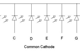
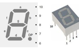
In 1910 Frank W. Wood made a board which can display number and after several modifications today it’s called 7-segment display. It is available in two configurations: common cathode and common anode. All the 8 LED terminals have their one end internally shorted and linked with the middle pins such that it serves as a common terminal (cathode or anode). 7 led are used to form the digits while the 8thone is for the dot which helps in identifying the correct orientation. It is widely used in digital clock, calculator, electronic meters and various other applications where numerical display is required. It can be used in place of dot matrix displays which are more complex than seven segment display. Seven segment displays can also be used to display some alphabets. Seven segment displays is a group of Light emitting diode (LED) arrange in figure of 8 pattern.
Random Number Generator Using 7 Segment Display
It is very simple and easy to construct project which will display random numbers from 0 to 7 on a 7 segment display. This circuit can serve as an alternative that can be used to replace the traditional dice while playing games such as snake ladder, monopoly etc. It uses NE555 which is a well known multivibrator IC. Here 555 timer IC is wired as an astable oscillator which provide a clock pulse to CD4017 IC.CD4017 which is a medium speed Johnson Counter that works at 10MHz and has 10 decoded outputs. CD4017 ICs are widely used in frequency dividers, binary counters, divide by N counters and register design applications and CD4511 which is a BCD to 7 segment decoder.
BCD to 7 Segment display Circuit
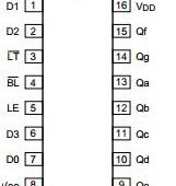
Many times we use LEDs in order to see binary outputs which are quite difficult to understand. The circuit described below will solve your problem as it will [[wysiwyg_imageupload::]]>display binary code on 7 segment displays, a very common and useful component of digital devices. It is based on CD4511, a CMOS BCD to seven segment latch/decoder and is used in various application like in clock, watches, computer, calculators etc. One thing to be kept in mind with this circuit is IC 4511 is used only for common cathode display. This IC provides the facility of 4-bit storage latch, an 8421 BCD-to-seven segment decoder. It also provides you the facility to check that all segments of 7 segment display are working properly or not (lamp test). For testing, momentarily make the pin low, in short used to test the display. Blanking input is used to turn off or vary the brightness of the display. Latch enable (LE) is used to store BCD codes.
Electronic voting machine using seven segment multiplexing with 8051 microcontroller (AT89C51)
This topic presents a basic approach to develop an electronic machine. The idea is to display the count of votes on a set of seven segment displays. A set of [[wysiwyg_imageupload::]]switches are provided through which a user can cast vote. After every cast of vote, the subsequent count can be seen on the seven segments. The segments and switches are controlled through AT89C51. For every candidate, a segment has been provided.This voting machine is designed for four candidates. The provision of casting vote has been provided by means of four tactile switches. These switches take manual inputs from the user and transfer them to the pins of controller. Based on these inputs, the vote count for different candidates is increased by AT89C51.Read more to find out how to program and design such a circuit.
Alarm Clock using 7-Segment Display and 8051 microcontroller (AT89C51)
An alarm clock is a clock that indicates a pre-set time by producing sound at that time. This functionality of digital clock is used to awaken people or remind them [[wysiwyg_imageupload::]]of something. This circuit is an extension to the digital clock with time setting option. Here an extra switch is provided to set the alarm. While the alarm is set, the clock time does not stop and runs in the background. The project is built around the 8051 microcontroller (AT89C51). The option to set alarm is provided by providing an extra switch S5, with the microcontoller At89C51, which is made active low.Whenever S5 is pressed, the time display goes off and only 1st segment is activated. But the clock time still runs in the background. In this mode, a segment can be selected in cyclic order by pressing S2. After selecting the desired segment, its value can be changed by using S3. Once the digits and hence the alarm is set, S4 is pressed to start the clock again. As soon as the set alarm time is reached, a buzzer gets signal from the microcontroller thus producing sound.
Digital Clock with time set option using seven segment and 8051 microcontroller
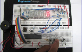
This digital clock not only displays time (on four seven segment displays) but also provides the user an option to set the time. For this the user has to first press [[wysiwyg_imageupload::]]the reset switch after which he/she can select and set a particular digit by incrementing its value. To run the clock with the set time, the user needs to press the start button. The seven segment and switches are interfaced with microcontroller AT89C51. This idea to provide option for setting time can be implemented in conjunction with the digital clock circuit. The control options for time setting are provided by means of tactile switches which are made active low. This circuit uses four such switches. As soon as S1 is pressed, the running clock stops and it goes into the reset mode where the first segment is activated. The segment to be set can be selected in cyclic order each time S2 is pressed. After selecting the desired segment, its value can be changed by using S3.
Seven segment multiplexing using 8051 microcontroller (AT89C51)- (Part 4/45)
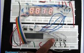
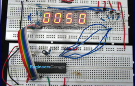
Many electronic devices use four seven segment displays to display their output. The four seven segment displays can be connected in two ways. One way is to [[wysiwyg_imageupload::]]connect the four displays to the four ports of the microcontroller. However this is not a good way, as this will block all the ports and we cannot use microcontroller for any other purpose.To overcome this problem, we use multiplexing of seven segment display. In multiplexing we use the concept of persistence of vision i.e., human brain cannot differentiate between two events occurring at a time difference of less than .04 sec. In this case the four digits are displayed one after the other so fast that the human brain cannot detect the difference. Although only one digit is displayed at a time it appears as a four digit number.The circuit presented here demonstrates the above principle in form of a counter which counts from 0 to 9999 with a small delay.
Digital dice using 8051 microcontroller (AT89C51)
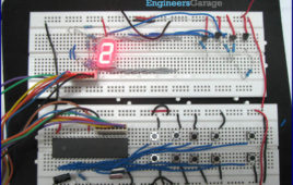
All of us have played the game of gambling and are well aware of the working of the dice. Here we are presenting a circuit to make a electronic digital dice with the [[wysiwyg_imageupload::]]help of a seven segment controlled by an 8051 microcontroller. We have already gone through the seven segment circuit interfacing (refer ‘interfacing seven segment’ section). The circuit can be divided into two units: the microcontroller unit and the seven segment unit. The microcontroller unit contains a microcontroller circuit (for microcontroller circuit details, refer ‘led blinking’ section) and the seven segment unit contains a seven segment circuit which is interfaced to the controller (for more details of seven segment circuit, refer ‘seven segment interfacing’ section). This circuit displays the numbers from 1 to 6 continuously and it halts at the position user wants and starts again from the same position with the next instruction of the user.
User input based seven segment display using 8051 microcontroller (AT89C51)- (Part 3/45)
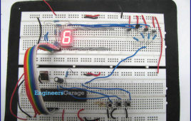
This article is a simple application built around the seven segment display. The circuit has ten inputs corresponding to digits zero to nine. Whenever an input is pressed the corresponding digit is displayed on the seven segment.The microcontroller used is AT89C51 which belongs to the 8051 series of microcontroller.The circuit can be divided into two units: the controller unit and the display unit. The controller unit consists of a microcontroller circuit. The microcontroller used here is AT89C51 . The display unit consists of a seven segment circuit which is interfaced to the microcontroller. The circuit is similar to the seven segment circuit with the only difference that here we have ten input pins. Each input pin corresponds to one of the digits to be displayed on the seven segment. Here the pin 0 to pin 7 of port P3, pin 6 and pin 7 of port P 1 are made the input pins. The output is sent to the seven segment through Port 2 of the microcontroller.
How to interface seven segment display with 8051 microcontroller (AT89C51)- (Part 2/45)
Seven Segment displays are used in a number of systems to display the numeric information. The seven segment can display one digit at a time. Thus the no. of [[wysiwyg_imageupload::]]segments used depends on the no. of digits in the number to be displayed. Interfacing seven segment with a controller or MCU is tricky. This article explains the interfacing of seven segment with MCU AT89C51. It displays the digits 0 to 9 continuously at a predefined time delay. Seven Segment are available in two configuration – (1) Common Anode (2) Common Cathode.Here common anode seven segment display is used because the output current of the microcontroller is not sufficient enough to drive the LED’s, similar to the case of driving an LED. The circuit diagram shows the connections of seven segment to the controller. The pins a to g of the Seven Segment are connected to the Port P2 of the microcontroller. The common pin of the seven segment is connected to Vcc. The ‘h’ has not been used, which is the dot pin of the controller.
Seven Segment Multiplexing using PIC18F4550 Microcontroller- (Part 4/25)
As explained earlier, a seven segment interfaced with PIC uses almost an entire port (minimum 7 pins) to display a value. But a real time application, like watch, [[wysiwyg_imageupload::]]calculator etc., usually requires at least 3-4 seven segments. In such a case it is not advisable to use a port of the controller for each seven segment. In these cases, multiplexing technique is used to work with more than one seven segment. Here multiplexing of four seven-segments has been explained withPIC18F4550 to display four-digit count from 0000 to 9999. The multiplexing concept is based on the principle of persistence of human vision. A human eye cannot detect a visual change if the frames change at a rate of 25 (or more) frames per sec. This means that if events occur continuously with a time difference of less than or equal to 0.04 sec (1/25 sec), then we cannot notice the transition between those events.
How to interface Seven Segment Display with PIC18F4550 Microcontroller- (Part 3/25)
A typical seven-segment consists of 8 LEDs arranged in a pattern to display values. A seven-segment can be either of the two types, namely, Common Anode (CA) and Common Cathode (CC). For more details, refer Seven segments. A single seven-segment requires a minimum of 7 data pins of controller to display different values. The connections…
Johnson Counter: How to use IC CD4033
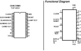
CD4033 is a Johnson counter IC commonly used in digital display. It has a 5 stage Johnson decade counter with decoder which convert the Johnson code to a 7 [[wysiwyg_imageupload::]]segment decoded output. Means it will convert the input into numeric display which can be seen on 7 segment display or with the help of LED’s.Advantage of this IC is it can be operated at high voltage of 20V. But is highly sensitive, can detect emf present in the atmosphere and is sensitive to static charge also. When you touch your finger at its input terminal its counter get started therefore care should be taken while using it. It can be used in various application like in 7 segment decimal display circuit, in clocks, timer etc. To understand its working first have a look on its pin diagram. Read more to find out how it is can be used in various applications.
How to display numbers and alphabet on 7 segment display?
Seven segment displays nowadays are commonly used in place of dot matrix display. They have found their use in places like microwave or fancy toaster oven or the same on washing machine but before using them in all these places you need to interface the 7 segment display with microcontroller or some more hardware will be required. But with the basic knowledge of 7 segments display you can use it in front of your shop or you can display your name on it. 7 segment displays numbers from 0 to 9 and some alphabets.7 segment display are labelled a to g and decimal point is usually known as DP. DP is the common point. In common cathode display they are connected to ground and rest pin are connected to supply. Similarly in common anode DP are connected to supply and rest are connected to ground. You can also use more than one display according to your requirement.

