The project aims at controlling a wheelchair by means of human voice. It enables a disabled person to move around independently, using a voice recognition application which is interfaced with motors. The prototype of the wheelchair is built using a micro-controller, chosen for its low cost, in addition to its versatility and performance in mathematical operations and communication with other electronic devices. The system has been designed and implemented in a cost effective way so that if our project is commercialized the needy users in developing countries will benefit from it.
Fig. 1: Prototype of voice controlled wheel chair for physically challenged people
Here we are using voice reorganization technology. So we are using HM 2007module to recognize the speech signal. This module is used to convert the voice signal into corresponding binary code that is given to the microcontroller, and the microcontroller gives the output according to the voice input.
Generally microcontroller generates codes in itsoutput according to the input. So using this module we can control the dc motor corresponding to the voice command.
Here there are five voice command is used for controlling the direction of the motor.
1. Forward
2. Backward
3. Stop
4. Right
5. Left
Working
Working with block diagram, circuit and PCB

Fig. 2: Block Diagram of voice controlled wheel chair for physically challenged people
· Microphone:
It is used to convert the voice signal in to electrical signal. Output of the MIC is given to the voice recognition Module.
· Microcontroller:
The microcontroller is semiconductor chip. It is programmable, multipurpose, multi functional. The AT89C51 is a low-power, high-performance CMOS 8-bit microcomputer with 8Kbytes of Flash programmable and erasable read only memory (PEROM).
The devices manufactured using Atmel’s high-density non-volatile memory technology and is-compatible with the industry-standard 80C51 and 80C52 instruction set and pin-out. The on-chip Flash allows the program memory to be reprogrammed in-system or by a conventional non-volatile memory programmer.
· Speed and driving:
The motor which we used is procured from AGNI MOTOR,BANGLORE has the following specifications:120W,9.8Nm,60 rpm with no load.Two 12V,32Ah lead acid AMARON batteries were purchased.we can increase speed of motor using
· Battery:
Here 12V battery is used for the motors to provide a sufficient power to the motors and here we are also used mechenisam charging of battery. So here we are used a battery charger for charging the battery.
· Voice recognization module:
The speech recognition system is acompletely assembled and easy to useprogrammable speech recognition circuit.Programmable, in the sense that you train the words (or vocal utterances) you want the circuit to recognize. This board allows you to experiment with many facets of speech recognition technology. It has 8 bitdata out which can be interfaced with anymicrocontroller for further development. Some of interfacing applications which can bemade are controlling home appliances, robotics movements, Speech Assisted technologies, Speech to text translation, and many more
Here we use a voice recognition module to control performance of the micro controller a microphone. Voice recognition module is trained by giving the 5 commands. The five commands are converted into hex file. These hex file points 5 address locations of AT89c52 microcontroller. When command is given the program in the corresponding and thereby controls the movement or rotation of the motor. This is the basic working principle of the ‘voice controlled wheel chair’. Voice is given to the voice recognition module through address location is executed and chair moves accordingly. The battery and battery charger unit is there for power supply.
Circuit Description
Circuit discription:
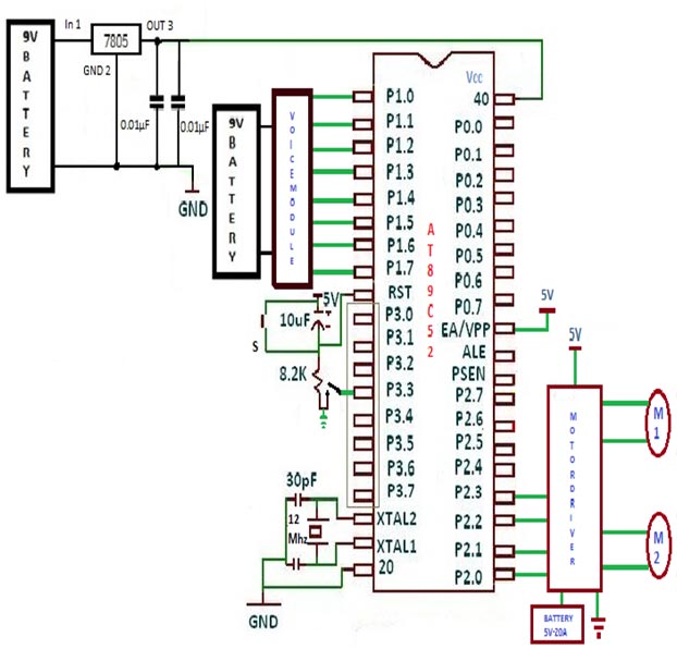
A. Whole circuit diagram of our project is shown above fig. 9v battery is connect across 100µF.here 7805 IC is used, this IC is used to give constant dc 5v.output of this Ic is connect to pin no 40 of microcontroller AT89C52.output of voice module is connected with port1 of the At89c52. Then output of port2 is given to input of motor driver circuit. which drive the motor in clockwise and counterclockwise.12v and 40A battery is connected with motor driver circuit.
B. Microcontroller IC receives 4-bit digital output from voice module. its port P1 pins P1.0 – P1.3. And interrupt signal is given to P3.3 (external interrupt 1) pin. It drives two DC motors through port P2 pins P2.0 – P2.3. A 12 MHz crystal with twoaock signal to micro controller. One push button switch (RST) in parallel with 100nF capacitor forms power on reset circuit to reset the micro controller.
C. It will control the motion of land rover depending upon the code it receives from given below in table:
|
INPUT |
INPUT AT PORT1 |
OUTPUT AT PORT2 |
WHEELCHAIR MOTION |
|
|
02 |
0010 |
0A |
1010 |
FORWORD |
|
08 |
1000 |
05 |
0101 |
BACKWORD |
|
04 |
0100 |
02 |
0010 |
LEFT |
|
06 |
0110 |
08 |
1000 |
RIGHT |
|
05 |
0101 |
03 |
0011 |
STOP |

Fig. 3: PCB Layout of Voice Sensitive Circuit for Wheel Chair
Track Layout of voice control wheel chair

Fig. 4: Track Layout of Voice Sensitive Circuit for Wheel Chair
List of Components
List of Components
|
Name of components |
Value |
|
|
|
|
RESISTOR |
10E |
|
|
|
|
CAPACITOR |
33pF |
|
|
|
|
IC |
AT89C52 |
|
|
|
|
WHEEL CHAIR |
– |
|
|
|
|
SOCKETS |
40 PINS AT89C52 |
|
|
|
|
VOICE RECOGNIZATION MODULE |
HM 2007 |
|
|
|
|
MISCELLANEOUS |
CRYSTAL |
|
|
|
|
MOTORS |
DC GEAR MOTOR |
|
|
|
|
DRIVING CIRCUIT |
|
|
|
|
|
|
|
|
|
|

Fig. 5: Image of Motor Driver Module
· Below table shows parameters and its range for driver.
|
Parameters |
Range |
|
Vcc (supply voltage) |
6 to 16 V DC |
|
Supply current |
20A continuous at 25c ;30A pulsed |
|
PWM frequency |
0 to 20 KHz |
|
VIL (low level logic input) |
>0.8V |
|
VIH (high level logic input) |
3.5V to 5V |
|
Output at diagnostic 1(ENA) and Diagnostic 2 (ENB) |
Open collector, internally pulled up at 5V |
· Below table shows controlling bits for motors.
|
A |
B |
OUTPUT |
|
0 |
0 |
STOP |
|
0 |
1 |
REVERSE |
|
1 |
0 |
FORWARD |
|
1 |
1 |
STOP |
200rpm DC motor

Fig. 6: Image of 200 RPM DC Motor
A. 200 RPM Side Shaft Super Heavy Duty DC Gear Motor is suitable for bigger robots small automation systems. It has sturdy construction with large gears. Gear box is built to handle the stall torque produced by the motor. Drive shaft is supported from both sides with metal bushes. Motor runs smoothly from 4V to 12V and gives 200 RPM at 12V. Motor has 8mm diameter, 19mm length drive shaft with D shape for excellent coupling.
Voice Recognition Module:
B. The speech recognition system is acompletely assembled and easy to useprogrammable speech recognition circuit.Programmable, in the sense that you train the words (or vocal utterances) you want the circuit to recognize. This board allows you to experiment with many facets of speech recognition technology. It has 8 bitdata out which can be interfaced with anymicrocontroller for further development. Some of interfacing applications whichcan bemade are controlling home appliances, robotics movements, Speech Assisted technologies, Speech to text translation, and many more.

Fig. 7: Image of Voice Recognition Module

Fig. 8: Circuit Diagram of HM2007 Voice Recognition System
Specifications:
|
PARAMETERS |
VALUE |
NOTE |
|
Input |
9 To 15 Volt Dc |
Use a commonly available 12V 500ma DC Adapter |
|
Output Data Voltage |
8 Bits At 5v Logic Level |
Any microcontroller like 8051, PIC or AVR can be interfaced to data port to interpret and implement specialized applications |
Working
Training Words for Recognition:
A. Press “1” (display will show “01” and the LED will turn off) on the keypad, then press the TRAIN key (the LED will turn on) to place circuit in training mode, for word one. Say the target word into the onboard microphone (near LED) clearly. The circuit signals acceptance of the voice input by blinking the LED off then on. The word (or utterance) is now identified as the “01” word. If the LED did not flash, start over by pressing “1” and then “TRAIN” key. You may continue training new words in the circuit.
B. Press “2” then TRN to train the second word and so on. The circuit will accept and recognize up to 20 words (numbers 1 through 20). It is not necessary to train all word spaces. If you only require 10 target words that are all you need to train.
Testing Recognition:
C. Repeat a trained word into the microphone. The number of the word should be displayed on the digital display. For instance, if the word “directory” was trained as word number 20, saying the word “directory” into the microphone will cause the number 20 to be displayed.
Error Codes:
D. The chip provides the following error codes:
55 = word to long, 66 = word to short, 77 = no match
Learning Memory:
E. To erase all words in memory press “99” and then “CLR”. The numbers will quickly scroll by on the digital display as the memory is erased.
Changing & Erasing Words:
F. Trained words can easily be changed by overwriting the original word. For instances suppose word six was the word “Capital” and you want to change it to the word “State”. Simply retrain the word space by pressing “6” then the TRAIN key and saying the word “State” into the microphone. If one wishes to erase the word without replacing it with another word press the word number (in this case six) then press the CLR key. Word six is now erased.
Simulated Independent Recognition:
G. The speech recognition system is speaker dependants, meaning that the voice that trained the system has the highest recognition accuracy. But you can simulate independent speech recognition. To make the recognition system simulate speaker independence one uses more than one word space for each target word. The word spaces 01, 02, 03 and 04 are allocated to the first target word programmed.
Programming
Programming for project
A. We used KEIL software for programming to control our wheel chair.

Fig. 9: Screenshot of C Code on Keil IDE used for Voice controlled Wheel Chair

Fig. 10: Screenshot of testing C Code on Keil IDE used for Voice controlled Wheel Chair
Charging unit for 12V & 40A battery
B. We have used 12V and 40A battery to supply both drivers. Charging unit required for this battery is shown in figure.
C. The 230V AC is given to transformer (step down type) 12-0-12V and 3A through fuse of 2A. This is used to provide protection to transformer from any high variation in input supply. Output of transformer is given to diodes which are used as rectifier and converts AC in to DC. Current up to 3A is limited for these diodes. One led is used to indicate that supply is ON. This led required maximum 5V to operate so we have used 1m? resistor to down the voltage. Switch is used to ON-OFF the supply.
Fig. 11: Circuit Diagram of Charger for Voice controlled Wheel Chair
How to run project
1. Switch on the power supply of voice module to provide sufficient voltage for proper working.
2. Switch on the interrupt switch and give your speech command as per requirement of movement of wheel chair to voice module.
3. After given the speech command switch off the interrupt switchto avoid any other noise interference to voice module from error.
4. Voice module generate hex code correspond to input speech. Ex, if we speak forward then output of voice module is 02h.
5. That code is applied to input port 1 of the AT89C52 micro controller.
6. Micro controller generate correspond code ex02h (0010) which is give to both motor driver to drive the motor in forward direction.
7. These steps are repeated for all commands.
You may also like:


Project Source Code
### Program for voice control wheelchair #includeunsigned char data byt=0xFF; void keydly() { int a,b; for(a=0;a<50;a++) for(b=0;b<1000;b++); } void int1() interrupt 2 { byt=P1; EA=0; keydly(); } void main() { P2=0x00; P1=0xFF; back:IE=0x84; byt=0xFF; while(byt==0xFF); switch(byt) { case 0xF2: P2=0x0A; break; case 0xF4: P2=0x08; break; case 0xF5: P2=0x03; break; case 0xF6: P2=0x02; break; case 0xF8: P2=0x05; break; } goto back; } ###
Circuit Diagrams
Project Video
Filed Under: Electronic Projects
Filed Under: Electronic Projects

Questions related to this article?
👉Ask and discuss on EDAboard.com and Electro-Tech-Online.com forums.
Tell Us What You Think!!
You must be logged in to post a comment.