Engineers Garage

  • Electronic Projects & Tutorials
    • Electronic Projects
      • Arduino Projects
      • AVR
      • Raspberry pi
      • ESP8266
      • BeagleBone
      • 8051 Microcontroller
      • ARM
      • PIC Microcontroller
      • STM32
    • Tutorials
      • Complete Sensor Guide
      • Engineering Deep Dives
      • AI
      • ARDUINO Compatible Coding
      • Audio Electronics
      • Battery Management
      • Beginners Electronics Series
      • Brainwave
      • Digital electronics (DE)
      • Electric Vehicles
      • EMI/EMC/RFI
      • EVs
      • Hardware Filters
      • IoT tutorials
      • LoRa/LoRaWAN
      • Power Tutorials
      • Protocol
      • Python
      • RPI Python Programming
      • Sensors
      • USB
      • Thermal management
      • Verilog
      • VHDL
    • Circuit Design
    • Project Videos
    • Components
  • Articles
    • Tech Articles
    • Insight
    • Invention Stories
    • How to
    • What Is
  • News
    • Electronic Product News
    • Business News
    • Company/Start-up News
    • DIY Reviews
    • Guest Post
  • Forums
    • EDABoard.com
    • Electro-Tech-Online
    • EG Forum Archive
  • DigiKey Store
    • Cables, Wires
    • Connectors, Interconnect
    • Discrete
    • Electromechanical
    • Embedded Computers
    • Enclosures, Hardware, Office
    • Integrated Circuits (ICs)
    • Isolators
    • LED/Optoelectronics
    • Passive
    • Power, Circuit Protection
    • Programmers
    • RF, Wireless
    • Semiconductors
    • Sensors, Transducers
    • Test Products
    • Tools
  • Learn
    • Design Guides
    • Learning Center
    • Tech Toolboxes
    • Tech Terms
    • Webinars & Digital Events
  • Resources
    • EE Training Days
    • LEAP Awards
    • Podcasts
    • White Papers
  • Guest Post Guidelines
  • Advertise
  • Subscribe

Speed and Direction Control of Stepper Motor using AVR Microcontroller- (Part 25/46)

By Ashutosh Bhatt January 29, 2014


Stepper motor can be termed as digital motor because it operates on pulses. Unlike AC or DC motor that rotates continuously, stepper motor rotates in steps. It rotates in number of steps as per applied number of pulses. Stepper motor is used in many applications like:

. Robotic application – to move robotic arm to specific position, to move robo-vehicle in specific direction at specific angle

· Disk drive application (CD drive, HDD) – to position reading head at specific position· Defence application – to fire a shell or to launch missile at perfect angle

· Domestic application – to open or close window shutter / curtain / blinds etc

· Communication application – to lock the position of satellite dish antenna at specific angle


There are different types of stepper motors permanent magnet, variable reluctance, unipolar, bipolar etc. In this project I have used unipolar type stepper motor with following ratings

·  Max rated voltage: –    5 V

·  Max rated current per coil: – 0.5 Amp

·  Step resolution: –    1.8 degree / pulse 

·  Max RPM: –    60In this project I am varying speed and altering rotating direction of motor. But to vary the speed or to alter the direction of motor one has to first understand how unipolar stepper motor rotates. So first let us understand how to rotate unipolar stepper motor
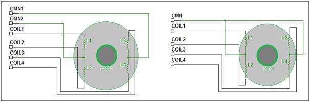
Diagram showing wiring of Stepper Motor

Fig. 1: Diagram showing wiring of Stepper Motor

In unipolar stepper motor there are four coils. There can be six terminals or five terminals. In six terminals stepper motor one end of two coils is shorted and taken out as common terminal. similarly for other two coils. These two common terminals are always connected to +Ve / -Ve terminal of supply. The remaining four terminals of each coil are used to rotate motor. In five terminals stepper motor one end of all four coils are shorted and taken out as single common terminal that is to be connected to +Ve / -Ve terminal.Now to rotate motor (clockwise or anticlockwise) pulses has to be applied to these four coil terminals in following sequence.

Step

clockwise

anticlockwise

Coil4

Coil3

Coil2

Coil1

Coil 4

Coil3

Coil2

Coil 1

Step1

0

0

0

1

1

0

0

0

Step2

0

0

1

0

0

1

0

0

Step3

0

1

0

0

0

0

1

0

Step4

1

0

0

0

0

0

0

1

Note – in the above sequence ‘1’ indicate the coils are given +Ve supply. The common terminal is connected to –Ve (Gnd) terminal.So as we apply this four steps sequence continuously, the motor will rotate clockwise or anticlockwise. Now to change the speed of motor we have to change pulse repetition frequency (PRF) that is the frequency of applied pulses. If PRF is increased the pulse duration decreases and speed increases and vice versa.  So this project demonstrates how to vary the speed and change the direction of given stepper motor using AVR microcontroller ATmega32. It alters pulse sequence to change the direction and varies pulse duration (PRF) to vary the speed of motor. So let us start with system block diagram.

 System Block Diagram

System block diagram: –
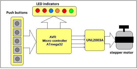
 

Block Diagram of AVR ATMega32 based Stepper Motor Controller

Fig. 2: Block Diagram of AVR ATMega32 based Stepper Motor Controller

The major building blocks of this system are as shown in figure that are ATmega32 and steeper motor driver chip ULN2003A. Along with them we need some push buttons for controlling and LEDs for indications. Each block is described briefly here.

Push buttons – five push buttons are given to run / stop, to vary speed and change direction of motor

button

function

Button 1

Run motor in clockwise direction

Button 2

Run motor in anticlockwise direction

Button 3

Stop motor

Button 4

Increase speed

Button 5

Decrease speed

ULN2003A chip – this chip takes input from micro controller and drives steeper motor. The microcontroller output current is not enough to drive motor directly. The chip has 7 Darlington pair drivers. It will provide up to 500 mA current to motor that is enough to drive it.

LED indications – Four LEDs are used for different indications

LED

colour

indication

LED 3

Blue

Blinks when speed in increased

LED 4

Orange

Blinks when speed is decreased

LED 5

red

Lits ON when speed limit is maximum

LED 6

red

Lits ON when speed limit is minimum


AVR micro controller – ATmega32 is low power, high performance, 8-bit, Advance RISC architecture based microcontroller. It has 32 KB of in system programmable FLASH. Also it has built in peripherals like 10-bit, 8 channel ADC, 4 PWM channels, 1 16-bit and 2 8-bit timers/counters, USART, SPI, IIC etc. In this system it performs following tasks

· Scans push buttons continuously to get user input

· Give different indications on LEDs

· Run or stop steeper motor

· Change direction of motor

· Varies speed of motor

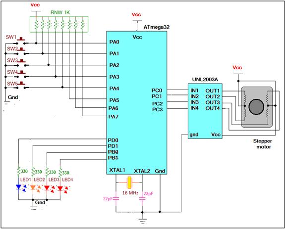
System circuit diagram: –

  The circuit is made up of ATmega32, ULN2003A and few discrete components like LEDs, registers, capacitors, push buttons etc

· 5 push buttons SW1 – SW5 are connected to PORTA pins PA0 to PA4. Also all port pins are pulled high through external pull up resistors as shown

· 4 LEDs LED1 – LED4 are connected to PORTD pins PD0 to PD3 through current limiting resistors

· PORTC pins PC0 to PC3 are connected to 4 inputs of UNL2003A chip

· 4 terminals of stepper motor are connected to output of ULN2003A chip

· Two common terminals of motor are connected to 5 V Vcc supply

· A 16 MHZ crystal with two 22 pF capacitor is connected to crystal input pins XTAL1 & XTAL2

· Vcc supply of 5 V is connected to required pins of both chips and pull up resistors

 Working & Operations

System working and operation: –

· Initially motor is stop. All the LEDs are OFF

· When SW1 is pressed momentarily, the motor starts rotating in clockwise direction

· Now if SW4 or SW5 button is pressed, the motor speed will increase or decrease. It is indicated by blink of LED1 or LED2

· If anyone keep on pressing SW4 or SW5 then speed will keep on increasing or decreasing. When max or min limit is reached, the corresponding LED3 or LED5 will be ON

· While motor is running in clockwise direction if SW2 is pressed, the motor will immediately start rotating in anticlockwise direction and vice versa

· Pressing SW3 will stop running motor

Program: –

Program is written in C language. Its compiled and simulated using AVR studio software. Complete program is made up of different functions

· Keydly() function – this function generates key debounce delay of approx 0.2 sec that is required when key is pressed

· Incspeed() function – this function decreases delay applied between pulse (increases PRF) fed to motor by decreasing time of delay loop library function. It also checks for maximum speed limit by checking min time for loop. If maximum speed limit is reached it turns ON LED3

· decspeed() function – this function increases delay applied between pulse (decreases PRF) fed to motor by increasing time of delay loop library function. It also checks for minimum speed limit by checking max time for loop. If minimum speed limit is reached it turns ON LED4

· clockwise() function – it continuously gives sequences of pulses as shown in table 1 to motor to rotate it in clockwise direction till any other button is not pressed

· anticlockwise() function – it continuously gives sequence of pulses to motor to rotate it in anticlockwise direction till any button is not pressed

· main() function – it initializes ports as input or output and then it scans all the buttons in continuous loop. 


Project Source Code

###

#include <avr/io.h>
#include <util/delay.h>
uint16_t t=50535;                   // time delay value for delay loop
void keydly()                             // key debounce delay
{
   uint8_t i;
   for(i=0;i<7;i++)

      _delay_loop_2(10000);             // delay loop library function with fixed delay

}

void incspeed()                 // increase speed of motor by

{

                PORTB = 0x00;

                if(t>20535) t=t-2000;                                       // decreasing time delay value if its min limit is

                if(t==20535) PORTB = 0x01;                         // not reached. For min limit give indication on LED3

}

void decspeed()                                                                               // decrease speed of motor by

{

                PORTB = 0x00;

                if(t<60535) t=t+2000;                                      // increasing time delay value if its max limit is not

                if(t==60535) PORTB = 0x02;                         // reached. For max limit give indication on LED4              

}

void clockwise()                                                                                // rotate motor clockwise

  {

                  while(PINA==0xFF)                                       // apply pulse sequence till no button is pressed

                                  {

                                                  PORTC=0x01;                   // apply pulse to 1st coil

                                                  _delay_loop_2(t);         // generate delay as per time delay value

                                                   PORTC=0x02;                  // apply pulse to next coil and like wise

                                                  _delay_loop_2(t);

                                                   PORTC=0x04;

                                                  _delay_loop_2(t);

                                                   PORTC=0x08;

                                                  _delay_loop_2(t);

                                  }           

  }

void anticlockwise()                                                        // rotate motor anti clockwise

  {

                  while(PINA==0x0F)                                       // apply pulse sequence till no button is pressed

                                 { 

                                                  PORTC=0x08;                   // apply pulse to last coil

                                                  _delay_loop_2(t);         // give delay as per time delay value

                                                   PORTC=0x04;                  // apply next pulses as per required sequence

                                                  _delay_loop_2(t);

                                                   PORTC=0x02;

                                                  _delay_loop_2(t);

                                                   PORTC=0x01;

                                                  _delay_loop_2(t);

                                  }                           

  }

int main(void)

{

    uint8_t r=0,d;                                                                                // run and direction flag

    DDRC=0xFF;                                                                   / / initialize ports as input and output

                DDRB=0x03;

                DDRD=0x03;

                DDRA=0x00;

                PORTC=0x00;

                PORTB=0x00;

                PORTD=0x00;

    while(PINA==0xFF);                                                   // wait till no key is pressed

loop:switch(PINA)

                  {

                                  case 0xFE:                                         // for 1st key

                                                                keydly();              // give key debounce delay

                                                                r=1;                        // set run flag

                                                                d=0;                       // clear direction flag for CLK direction

                                                                clockwise();        // start rotating motor clock wise

                                                                break;

                                  case 0xFD:                                         // for 2nd key

                                                                keydly();              // key debounce delay

                                                                r=1;                        // set run flag

                                                                d=1;                       // set direction flag for ACLK direction

                                                                anticlockwise(); // start rotating motor anticlockwise

                                                                break;

                                  case 0xFB:                                         // for 3rd key

                                                                PORTC = 0x00;   // stop motor

                                                                r=0;                        // clear run flag

                                                                PORTB = 0x00;   // all indication off

                                                                break;

                                  case 0xF7:                                         // for 4th key

                                                                PORTD=0x01;     // give indication on  LED1

                                                                keydly();

                                                                PORTD=0x00;

                                                                incspeed();         // increase speed           

                                                                if(r==1)                 // if motor was running

                                                                  {

                                                                                if(d==0) clockwise();                       // check direction and

                                                                                else anticlockwise();                       // keep it running

                                                                  }

                                                                 break;

                                  case 0xEF:                                         // for 5th key

                                                                PORTD=0x02;     // indication on LED2

                                                                keydly();

                                                                PORTD=0x00;

                                                                decspeed();       // decrease speed

                                                                if(r==1)                 // if motor was running

                                                                  {

                                                                                if(d==0) clockwise();                       // check direction and

                                                                                else anticlockwise();                       // keep it running

                                                                  }

                                                                 break;                                 

                  }                                                              

      goto loop;                                                                     // continuous loop

}                         

###


Circuit Diagrams

Circuit-Diagram-AVR-ATMega32-Based-Stepper-Motor-Controller

Project Video


Filed Under: Electronic Projects
Tagged With: atmega16, avr, step motor, stepper motor
 

Next Article

← Previous Article
Next Article →

Questions related to this article?
👉Ask and discuss on Electro-Tech-Online.com and EDAboard.com forums.


Tell Us What You Think!! Cancel reply

Log in to leave a comment:

Lost your password?

Don't have an account? Register here

Submit a Guest Post

submit a guest post

EE TECH TOOLBOX

“ee
Tech Toolbox: Wide Bandgap Semiconductors
Moving from silicon to GaN or SiC feels like a whole new ballgame, doesn’t it? It isn’t just about faster switching; it’s about managing the layout parasitics and thermal realities that come with that speed. This month’s Tech Toolbox features a curated eBook that tackles these design hurdles head-on.

EE Learning Center

EE Learning Center
“engineers
EXPAND YOUR KNOWLEDGE AND STAY CONNECTED
Get the latest info on technologies, tools and strategies for EE professionals.

HAVE A QUESTION?

Have a technical question about an article or other engineering questions? Check out our engineering forums EDABoard.com and Electro-Tech-Online.com where you can get those questions asked and answered by your peers!


RSS feed: EDABOARD.com Discussions. EDABOARD.com Discussions.

  • Which protocol is more suitable for NFC wireless charging?
  • Choosing a Suitable Capacitor for Power Supply Smoothing
  • coherent vs. incoherent receivers
  • Ground pour won't go to GND vias in KICAD
  • review request: pico expansion board for controlling 4-pin 12v fans

RSS feed: Electro-Tech-Online.com Discussions Electro-Tech-Online.com Discussions

  • DS3231 RTC + 24C32 EEPROM I²C Module (OshonSoft)
  • 4060 counter doesn't stop ?
  • Request for a 5W transistor controlled LED flash light controller circuit review
  • My Advanced Realistic Humanoid Robots Project
  • Portable charger for my mate's new leg

Featured Tutorials

VHDL Series (1-24)

  • VHDL Tutorial 17: Design a JK flip-flop (with preset and clear) using VHDL
    VHDL Tutorial 17: Design a JK flip-flop (with preset and clear) using VHDL
  • VHDL Tutorial 18: Design a T flip-flop (with enable and an active high reset input) using VHDL
    VHDL Tutorial 18: Design a T flip-flop (with enable and an active high reset input) using VHDL
  • VHDL Tutorial – 19: Designing a 4-bit binary counter using VHDL
    VHDL Tutorial – 19: Designing a 4-bit binary counter using VHDL
  • VHDL Tutorial – 20: Designing 4-bit binary-to-gray & gray-to-binary code converters
    VHDL Tutorial – 20: Designing 4-bit binary-to-gray & gray-to-binary code converters
  • VHDL Tutorial – 21: Designing an 8-bit, full-adder circuit using VHDL
    VHDL Tutorial – 21: Designing an 8-bit, full-adder circuit using VHDL
  • VHDL Tutorial – 22: Designing a 1-bit & an 8-bit comparator by using VHDL
    VHDL Tutorial – 22: Designing a 1-bit & an 8-bit comparator by using VHDL
More Tutorials >

Recent Articles

  • Teradyne launches 24-slot tester for edge AI devices
  • Stackpole adds 25 mΩ and 30 mΩ sensing values
  • Novotechnik LWX transducers provide IP67 position measurement
  • TDK varistors provide 15 kV ESD protection
  • Microchip POL-05-20S-T delivers 20 A for space processing

EE ENGINEERING TRAINING DAYS

engineering
Engineers Garage
  • Analog IC TIps
  • Connector Tips
  • Battery Power Tips
  • EDABoard Forums
  • EE World Online
  • Electro-Tech-Online Forums
  • EV Engineering
  • Microcontroller Tips
  • Power Electronic Tips
  • Sensor Tips
  • Test and Measurement Tips
  • 5G Technology World
  • Subscribe to our newsletter
  • About Us
  • Contact Us
  • Advertise

Copyright © 2026 Arrowfly LLC. All Rights Reserved. The material on this site may not be reproduced, distributed, transmitted, cached or otherwise used, except with the prior written permission of Arrowfly
Privacy Policy

Search Engineers Garage

  • Electronic Projects & Tutorials
    • Electronic Projects
      • Arduino Projects
      • AVR
      • Raspberry pi
      • ESP8266
      • BeagleBone
      • 8051 Microcontroller
      • ARM
      • PIC Microcontroller
      • STM32
    • Tutorials
      • Complete Sensor Guide
      • Engineering Deep Dives
      • AI
      • ARDUINO Compatible Coding
      • Audio Electronics
      • Battery Management
      • Beginners Electronics Series
      • Brainwave
      • Digital electronics (DE)
      • Electric Vehicles
      • EMI/EMC/RFI
      • EVs
      • Hardware Filters
      • IoT tutorials
      • LoRa/LoRaWAN
      • Power Tutorials
      • Protocol
      • Python
      • RPI Python Programming
      • Sensors
      • USB
      • Thermal management
      • Verilog
      • VHDL
    • Circuit Design
    • Project Videos
    • Components
  • Articles
    • Tech Articles
    • Insight
    • Invention Stories
    • How to
    • What Is
  • News
    • Electronic Product News
    • Business News
    • Company/Start-up News
    • DIY Reviews
    • Guest Post
  • Forums
    • EDABoard.com
    • Electro-Tech-Online
    • EG Forum Archive
  • DigiKey Store
    • Cables, Wires
    • Connectors, Interconnect
    • Discrete
    • Electromechanical
    • Embedded Computers
    • Enclosures, Hardware, Office
    • Integrated Circuits (ICs)
    • Isolators
    • LED/Optoelectronics
    • Passive
    • Power, Circuit Protection
    • Programmers
    • RF, Wireless
    • Semiconductors
    • Sensors, Transducers
    • Test Products
    • Tools
  • Learn
    • Design Guides
    • Learning Center
    • Tech Toolboxes
    • Tech Terms
    • Webinars & Digital Events
  • Resources
    • EE Training Days
    • LEAP Awards
    • Podcasts
    • White Papers
  • Guest Post Guidelines
  • Advertise
  • Subscribe